Dual Gradient Drilling in Deep Water Wells
Introduction
The oil reserves of Russia’s continental shelf fields under development are decreasing. The domestic oil and gas companies are investing more and more into geological exploration on the continental shelves of the Kara Sea, Black Sea, Sea of Okhotsk as well as other areas [1,2].
The cost of constructing prospecting wells in these waters, let alone northern arctic waters, is several times higher than well constructions costs on the continental shelf. With high daily rate costs of operating offshore drilling platforms or ships, the longer and heavier strings, as well as the logistics of suppling equipment and the crew to the rig.
The complexity of offshore wells grows further with deep-water drilling. As sea depths increase, the lithologic pressure gradient and hydraulic fracturing pressure of the rock decrease, which narrows the selection range for circulating fluids, and results in the need to increase the number of production casing strings.
These factors lead to the necessity to search and introduce innovative techniques and technologies for construction of offshore deep-water wells. One of such perspective directions to solve this problem is the technology of Managed Pressure Drilling (MPD) in the “well-formation” system [3]. The use of the dual gradient drilling system is a variant of this technology, which opens new horizons in deep-water drilling.
Dual Gradient Drilling is One of the Deep-Water Drilling Solutions
When conventional drilling technology is applied to an offshore well, the annulus between the drill string and the inner wall of the riser string is filled with drilling mud of the same weight as in the annular space of the open (uncased) hole. As we know [3], the drilling mud weight is selected based on the conditions for creation of uplift pressure on horizons with the maximum formation pressure value. This gradient between the bottom-hole pressure and the formation pressure prevents the reservoir fluid from entering the well. The bottom-hole pressure within the borehole, however, must be lower than the pressure in the formation, to prevent breaking the formation.
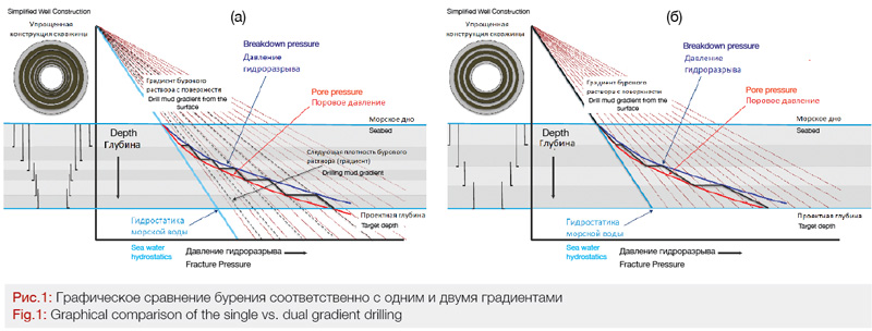
In deep-water wells (such as, in the Black Sea or the Gulf of Mexico), one can often encounter horizons having a narrow margin between the pore pressure and formation breakdown pressure. This narrow margin is, as a rule, the result of the abnormally high pore pressure and/or low formation breakdown pressure, due to the fact that the formation rock strata are additionally pressurized with sea water, which requires a greater number of production strings to be used in comparison with the wells of similar depth on the continental shelf. Fig.1(a) presents the values for production tubing string setting depth and separation for incompatible formations.
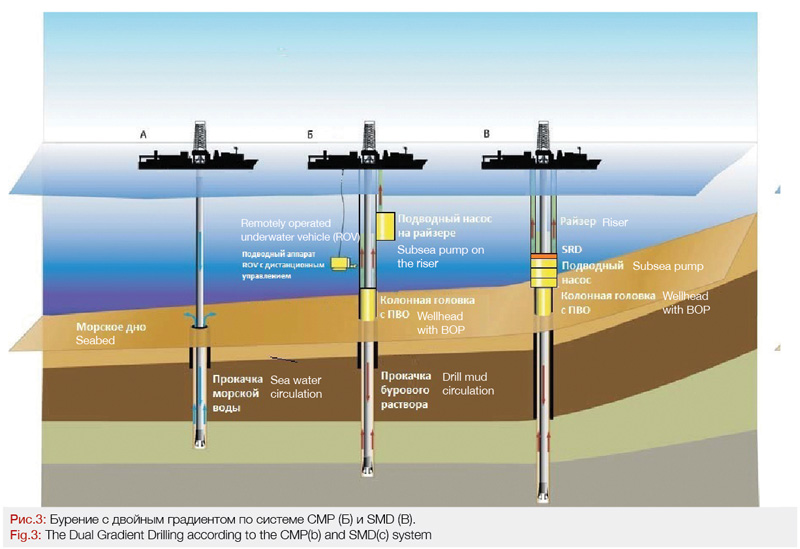
One of the possible ways to solve this problem has been the use of the double-density drilling system, or the dual gradient drilling system, as it is often called [4]. In comparison to conventional single gradient drilling, two hydrostatic gradients are used in the dual gradient drilling system. The gradient between the sea water pressure and the sea surface is used to control the well, while the drilling mud gradient between the sea bed and the bottom-hole area is used to secure the stability of the wellbore and to remove cuttings. Figuratively speaking, the drilling rig is located on the seabed, since the overlap of the water depth is balanced with the sea waterline gradient (Fig. 1b). It is important to note that the dual gradient drilling has been already applied in drilling of pilot boreholes or upper sections of wells before the BOP equipment is installed, as it is shown in Fig.3a.
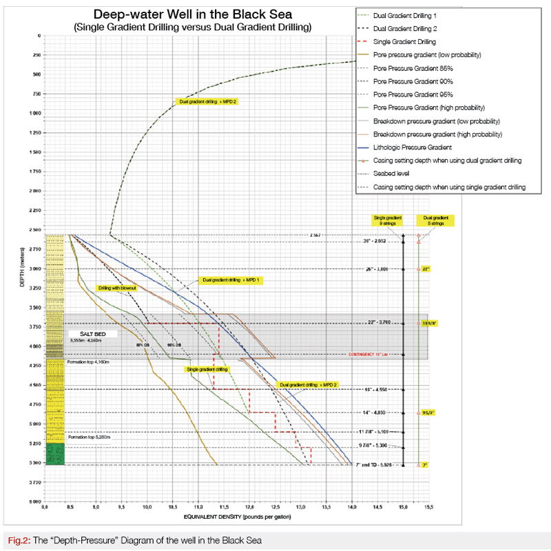
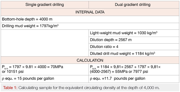
Two fluids inside the annular space can result in more favorable well profile pressures compared with conventional drilling. Fig.2 presents the pressure profile of one of the deep-water wells in the Black Sea. The dual gradient system transforms the general pressure profile, depending on the depth, compared with the conventional drilling, and provides a greater drilling margin due to shifting the pressure profile leftward (see Table 1).
The drilling of well’s upper intervals, down to the depth of 2,652 meters and 3,000 meters, is conventionally carried out with the return of drilling cuttings to the seabed (Drilling with blowout is presented in Figure 2). After running and the cementing of the 22” production string and the installation of risers with submersible blow-out preventor equipment, we recommend dual gradient drilling down to 3,700 meters. Hereafter the 13 5/8” production string is run and cemented, and the drilling is continued through the salt formation, using the dual gradient drilling technique, down to the depth of 4,850 meters (Figure 2 illustrates the dual gradient drilling + MPD1). Thereafter, the 9 5/8” production string is run and cemented, and the dual gradient drilling is carried out down to the target depth of 5,526 meters (The dual gradient drilling + MPD 2 is illustrated in Figure 2).
The single drilling gradient is marked with red dashed line in Figure 2. Using this technique, there are a higher number of incompatible intervals; therefore, it is necessary to run 9 production strings, instead of 5, when the single gradient drilling technique is used.
The Science and Technology Research of the Dual Gradient Drilling Systems
The dual gradient drilling is referred to one of the varieties of the managed pressure drilling (MPD). Let us consider some systems and technologies used “after the BOP installation”, which have passed field trials.
Leading western oil companies have invested millions of dollars during the last 20 years (up to 2011) into the technologies of the dual gradient drilling, such as:
1. Subsea mud lift pump (SMD);
2. Controlled Mud Pressure system (CMP);
3. Continuous Annular Pressure Management System (CAPM).
“Chevron” [5,6] was one of the initiators of the development of the subsea mud lift pump system (SMD). SMD employs massive subsea pumps installed subsea, above BOP equipment (sea Figure 3b).
22 companies within Europe, the North and South Americas took part in the first phase of this development. The project participants arrived at a common view regarding the configuration of the necessary equipment and they determined that conventional approaches are quite applicable both in the sphere of drilling operations and for well control. The second phase of the development started in 1998, with participation of four operator companies, four contractors and one manufacturing company, aimed at the development of the most significant parts of the equipment. Elaborating the drilling and well control procedures was also progressing at this time, which included the establishment of pre-job training schools for teams involved in dual gradient drilling.
Let us describe the operational principle of the SMD technology: the subsea pump sucks drill mud from the annular space above the BOP equipment and pumps it up to the surface using the lines attached to riser. This subsea pump that lifts the drill mud up to the surface mechanically isolates the return line from the well’s annular space and maintains its pressure which is consistent with the hydrostatic pressure of the sea water column. Thereby the dual gradient pressure (from the side of the sea water and drilling mud) is maintained in the well’s annular space. As a result of pumping the drill mud out of the annular space up to the surface, an underbalance pressure differential develops between the annular space and drill pipes which are filled with drill mud. Therefore, the “drill pipe and annular space” system becomes unbalanced. The success of drilling and well control with the use of this subsea system of lifting drill mud up from the sea bed depends on the efficiency of controlling the unbalanced U-pipe, with the use of a special downhole deployment valve, located above the drill bit.
In addition to the mud lift pump, as part of the joint industrial project, a subsea rotating device (SRD) was developed, and mud solids processing unit (SPU) as well. The SRD (seal assembly with bearings) provides the outlet of drill mud from the annular space into the suction line of the subsea pump. The mud solids processing unit (SPU) is located between the SRD and the subsea pump and makes it possible to crush solid parts of drill cuttings down to the size of less than 38 mm. All of the cutting parts that are lower than that size pass this unit without crushing.
To implement the SMD technology, the drilling contractor “Pacific Drilling” reconstructed its sea drilling ships “Pacific Santa Ana”, “Pacific Khamsin” and Pacific Sharav”. From 6 to 7 drilling mud pumps, having a pressure up to 510 atmospheres, were installed on each of the ships.
The Company AGR, jointly with three major operators, within the frameworks of the Norway’s Research Program Demo 2000, developed the Controlled Mud Pressure system (CMP), which is illustrated in Figure 3b.
The CMP system’s operational principle is as follows: a pump is hooked on the riser at a certain depth above the sea bed. The pump sucks drill mud from the well above the BOP equipment and returns it to the drilling rig using the outside line. The pump makes it possible to control the level of sea water and drill mud inside the riser, thereby controlling the bottom-hole pressure.
A similar system, resembling the one implemented by AGR, was developed by the company Ocean Riser Systems AS, which was titled ‘Low Riser Drill Mud Return System’ (LRRS). The operational principle of the LRRS system is as follows: a pump is hooked up on the drilling rig to a certain sea depth. A flexible pipe is attached from the pump to the riser where drill mud is sucked and returned to the drilling rig through the outside line. The riser is filled with nitrogen, instead of the displaced mud, thus, the created hydrostatic column of gas/liquid makes it possible to control the pressure.
The company Trancoocean chose a different way and conducted laboratory experiments of the CAPM system (Continuous Annular Pressure Management) [7,8].
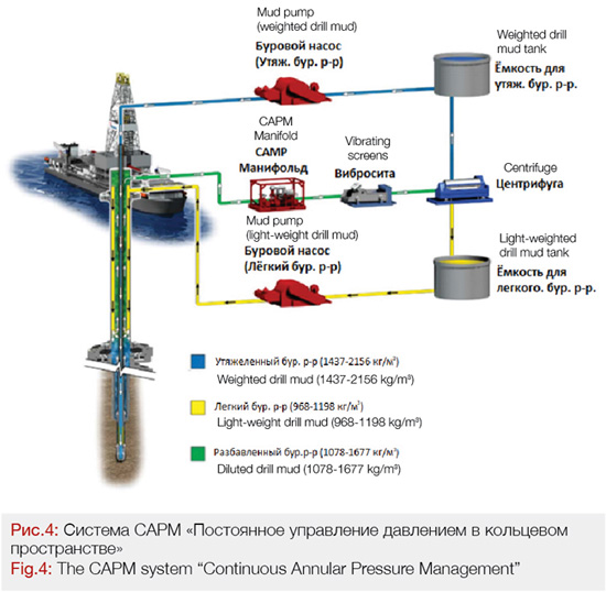
The operational principle of the CAPM system is illustrated in Figure 4: low density drilling mud (light-weight drilling mud) is pumped into the annular space using the kill lines. It is mixed, above the low riser package, with heavy-weight drilling mud delivered from the bottom-hole to the surface. Therefore, a diluted drill mud is created inside the riser. The diluted drill mud, when on the surface (a platform or a ship) passes through the treatment system and reaches a centrifuge where it is separated back into light-weight and heavy drilling mud. As a result of this, the bottom-hole pressure is formed as a sum of hydrostatic pressure of the columns of the heavy and diluted drill muds.
The centrifuge is a critical component of the CAMP system, which enables the separation of the diluted drill mud (1,076 to 1,677 kg/m3) into the weighted (1,437 to 2,156 kg/m3) and light-weighted drill mud (1,078 to 1,677 kg/m3). The field tests of this centrifuge, with consumption rate of 1,897 l/min, were successfully carried out on drill ship, Discoverer Enterprise, at the end of 2008.
Many research activities toward the dual gradient drilling were suspended after 2010, probably due to the fact that one of the major brand ambassadors of the dual gradient drilling, BP, suffered great losses after the disaster in the Gulf of Mexico’s Macondo field. [9,10].
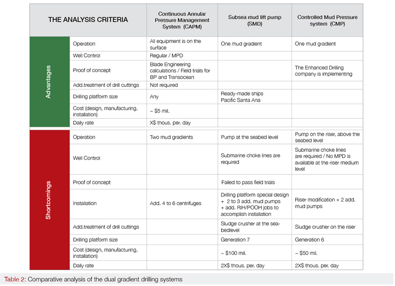
Table 2 presents the comparative analysis of the dual gradient drilling systems, where the main criteria are also introduced, which, to our mind, have an influence on Contractor’s decision to apply innovative equipment and technologies at oilfields.
Based on the implemented analysis, it is possible to conclude that, in case of the equipment located below sea level (the SMD and CMP systems), there exists a probability of downtime for overhauls, and the complications with well control are quite likely in case of gas blowouts. The analysis also testifies that one of the most perspective dual gradient drilling techniques is the CAPM system, Continuous Annual Pressure Management.
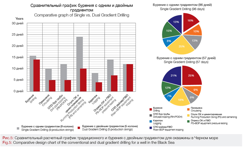
The potential economic effect from the use of the dual gradient system is presented in Figure 5, using the example of the mentioned Black Sea deep-water well. The cost of one day’s construction of a deep-water well (including all the materials and services), when using the conventional method, amounts to 1 mil USD. When using the dual gradient drilling system, the construction of a such well would take 57 days (instead of 96 days of the conventional method), therefore, the economic effect is estimated as much as 39 mil USD. The maximum effect is associated with savings on the costs of production strings, cement, drilling mud and time spent for RIH/POOH (run-in-hole/put-out-of-hole) operations.
Conclusion
1. The dual gradient drilling opens up broad horizons in drilling of deep-water wells with narrow ”drilling margins”. The reduction of well construction cost by up to 40% may contribute to the expansion of geological prospecting works in the seas of Russia.
2. The dual gradient drilling potentially makes it possible to qualitatively perform drilling in a formation due to reduced skin effect, as well as reach geological targets of greater depths of water, and drill in with the column with a diameter of 12 ¼ “- 8 ½”.
3. The dual gradient drilling system actually releases the riser from heavy drill mud. Therefore, the riser tension can be reduced, which would considerably raise the maximum depth of the waters where less powerful drilling rigs can work, or the allowable current load could be increased for those drilling rigs working in the conditions of shallow waters.
4. Drilling ships have been technically equipped and ready for the dual gradient drilling. Some dual gradient drilling systems have passed the field trials.
5. Introduction of new technology always demands an approach based on the evaluation and assessment of risks and design codes. Efforts are presently made to develop ruling documents and standards in the field of the dual gradient drilling (see NORSOK D-010 и DNV-OS-E101). Field staff retraining shall be an important task to facilitate the introduction of the dual gradient drilling systems.
6. On the 22nd December 2018, the RF Government issued an Ordinance #2914 “About the Approval of the Strategy for the Development of the RF Mineral-Raw Material Base for the Period before 2035” [11]. The given strategy provides for measures to develop the continental shelf as well, including the development of the blind and deep-seated deposits. The innovative systems for the oil-and-gas producing complex, presented in the given article may become an important prerequisite to achieve those set goals.
References:
1. Bogoyavlensky V.I. “Prospects and problems for development of oil and gas fields in Arctic shelf”: “Drilling and Oil” journal, 2012.
2. Volkov V.V, Shmal G.I. “Why does Bazhen skid?”: “Drilling and Oil” journal, 2019.
3. Chernukhiv V.I. “Development of technology for drilling wells with managed pressure drilling”: dissertation, Stavropol, 2005.
4. Smith, J.R.“Dual Density Drilling Fluid Systems to Enhance Deepwater Drilling”: presentation at Louisiana State University, 2004.
5. Peterman, C.P.“Riserless and MudLift Drilling – The Next Steps in Deepwater Drilling”: presented Offshore Technology Conference, Houston, 1998.
6. Forrest N., Bailey T., Hannegan D. “Sub Sea Equipment for Deep Water drilling Using Dual Gradient Mud System”: SPE/IADC 67707, 2001.
7. de Boer L. “Method and apparatus for varying the density in drilling fluids in deep water oil drilling applications,” United States Patent 6,536,540, 2003.
8. de Boer L. “DGS Dual Gradient Drilling System,” presentation in meeting of the Drilling Engineering Association, Houston, 2003.
9. Malyukov V.P., Sushok A.A. “Technological, environmental and economic problems resulting from the accident at Macondo well of British Petroleum in Gulf of Mexico”: RUDN University Bulletin, 2013.
10. News “BP was ordered to pay $21 billion for the accident in Gulf of Mexico”, 2015. [Electronic resource], Access mode: https://burneft.ru/main/news/10773,
11. The Government of Russian Federation. “Development Strategy for Mineral Resources Base of Russian Federation until 2035”: No. 2914-r, Moscow, 2018.
Authors:
Ganiev R.I., Technical Consultant, DGD LLC
Luc DeBoer, CEO, DGD LLC

