Electrical Equipment & Controls for Top Drive Systems
O. V. Nikulin, Lead Power Engineer, Tatburneft Management Company, PhD
V. A. Shabanov, Professor, Ufa State Petroleum Technological University, PhD
The top drive system (TDS), an oil and gas drilling technology, is becoming very widespread lately. Both imported and domestic drilling rigs are equipped with such a system. Basically, the top drive is a travelling rotary mechanism with a swivel provided with a mechanical handling system, or a power swivel. Its use eliminates the kelly and rathole and greatly facilitates the labor of the floormen since the elevator is automatically moved to the required position. Drilling can be done with stands rather than with single drill pipes (singles).
Further, the use of top drive system is required by the oil safety rules if the horizontal section exceeds 300 m [1]. The TDS general arrangement is shown in Fig. 1.

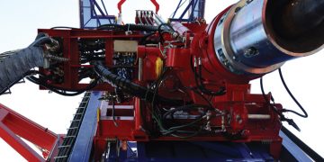
The top drive system attaches to the travelling block with hanger 1; the entire system moves vertically along guides 2. The system centerline is aligned with the well centerline. The power train contains squirrel-cage induction motor 3 and transmission 4. Drilling mud is supplied to pipe 5 through a flexible hose. The power swivel hangs up elevator 7 to latch the box end of the drill pipe with links 6 during handling.
The elevator is removed for drilling and the upper end of the drill pipe is spun up to stabbing guide 8 which is essentially an output shaft of the power train. When required the drilling string is reversed by reversing the drilling motor. Reactive torque generated by top drive system operation is absorbed by guide runners 2.
Induction motor 3 is the drilling motor that has a cooling system including cooling fan motor 9 and air duct 10. On motor shaft 9 encoder 11 provides speed feedback.
Through drilling motor 3 (Fig. 1) the top drive system [1] supports
• Drill string rotation during drilling, pipe handling, forward and back reaming and hole opening
• Spin-up, make-up, break-out, and spin-out of the drill strings; making up connections with a torque set by the driller
• Drill string rotation during DTH drilling
Through links 6 (Fig. 1) equipped with hydraulic link tilts 12 and holding tongs 13 to latch pipes the top drive system [1] supports
• Pipe handling
• Casing running
• Drilling with stands and singles
Wells flushing out and drill string reciprocation and cleaning during emergency and mitigation response activities are through pipe 5 incorporated into the top drive system.
The key top drive system benefits are
• Reduced scope and time of secondary operations (e. g., adding new pipes during drilling)
• Underreaming while tripping in and out
• Precision well placement for directional drilling
• Reduced time of the drill crew’s initial actions at the first indications of gas, water or oil ingress and diminished risk of a kick through the drilling string
• Diminished risk of drill tool sticking
• Facilitated casing running in the tight spots through rotation and flushing
• Enhanced drill crew safety
• Reduced drilling time and well construction time in general [1].

Figure 2 shows a top drive system speed/torque curve. The A-B section is a constancy curve for the power generated by the electrical drive and the B-C curve is a torque constancy curve. The maximum «braking» moment is reached at point D. Additional strict limitation on torque (the А–А1 section) is effected in the minimum torque mode.
Any of the modes discussed above is selected by the driller with help of relevant switches on the panel. A minimum torque mode (the А–А1 section) is selected for turbo drilling with simultaneous rotation of the drilling string. The constant power mode is used for drilling with the TDS drilling motor that transmits torque to the drill pipes. The constant torque mode (the B-C section) is used for pipe recovery, etc. Operation within the C-D section is for drill pipe spin-in and spin-out.
The power train of TDS is set up as a transformer-rectifier-inverter (Fig. 3). The transformer T steps down voltage from 6kV to 600V. The diagram includes the commutating inductors L at the input of the rectifier B and filtering inductors at the output of the inverter И to neutralize higher harmonics. The diagram features a TDS dynamic braking unit to remove extra power to the braking resistor R.

The three phase sine-wave input voltage with a constant amplitude and frequency is rectified in the rectifier B and then converted in the inverter И to alternating voltage with a variable frequency and amplitude. Output frequency fвых. and voltage Uвых. are adjusted by the inverter through high-frequency pulse-width modulation. Pulse-width modulation is described by a modulation period within which the stator winding of the motor is alternately coupled to the positive and negative poles of the rectifier. Coupling time for each winding is sinusoidally modulated within the pulse repetition period. The maximum impulse length is at the middle of the half-wave and decreases by the start and end of the half-wave. As such the inverter control system provides for the pulse-width modulation of the voltage applied to the motor windings. Voltage amplitude and frequency are defined by the characteristics of the modulating sine function. This way alternating voltage with a variable frequency and amplitude is produced at the converter output. Adjusting frequency and amplitude of the supply voltage supports better utilization of motor capacity by the drive operation in the constant power or constant torque modes [3, 4, 5].
Shaft horse power of the TDS drilling motor in different modes can be represented as a sum of three components:
• Horse power used for idle rotation of the drilling string Nх.в.
• Horse power used for rock breakdown at the bottom hole Nзаб.
• Drive mechanism horse power losses Nп..
Horse power used for idle rotation of the drilling string is determined based on a multitude of parameters: well depth, diameter and course, drilling practices, rock condition and drilling mud type. For operational calculations the following empirical equations can be used for straight holes with a maximum angle of 75° [3]:
Nх.в=55.8∙10-4k1∙k2∙k3 (1+0.44∙cosβ∙(0.9+20∙δ))∙k4∙q∙d∙n1.83∙L0.75
(1)
where k1: Drill pipe connection type factor (k1=1 for flush coupled pipes; k1=1.3 for box- and-pin ends)
k2: Mud type and dope use factor (k2=1.1÷1.3 for mud laden fluid flushing;
k2=1 for water flushing; k2=0.4÷0.6 for dope or emulsion mud)
k3: Hole wall factor (k3=1 for normal section; k3=1.5÷2 for difficult wells)
k4: Drill pipe material factor (k4=1 for steel drill pipes; k4=0.75 for aluminum drill pipes)
δ=(D–d)/2: Gap between hole walls and drill pipes, m, where D is the well diameter, m
d: Drill pipe diameter, m
q: Weight of 1m of drill pipes, kg/m
n: Bit speed, s-1
LWell depth, m
cosβWell angle cosine
A semi-empirical equation suggested by A. E. Saroyan [6] is used to determine the horse power required for idle rotation of a steel drill string when drilling wells with an angle less than 5° [6]:
Nх.в=13.5·10–8∙L∙d2∙(60∙n)1.5∙D0.5∙γж (2)
where γж: Mud weight, N/m3.
Nх.в decreases with the decrease in the pipe specific gravity for the light alloy pipes.
Horse power for rock breakdown during drilling depends on the rock breakdown tool type and drilling parameters.
For hard metal bit drilling the horse power used for rock breakdown is determined by the following equation
Nзаб=5.3·10-4·0.1·P·60·n·Dср.k·(0.137+μ) (3)
where Р: Axial load, N
Dср.k: Average bit diameter, m
Dср.к=D1k+D2k/2 (4)
where D1k , D2k: Bit outside and inside diameter, m
μ:Friction coefficient between cutting insert and bottom hole rock
Friction coefficient between cutting insert and rock is a function of many factors and an approximate value. It is related to the drilling parameters, drilling fluid composition, rock drilled and a range of other factors.

The μ values for different rock types are shown in Table 1.
For drilling with a diamond core bit
Nзаб = 2·10-4∙0.1·P·60·n∙Dср.к.. (5)
For none-core drilling
Nзаб=(3÷4) ∙10-4∙0.1∙P∙60∙n∙ D. (6)
Horse power used at the bottom hole when drilling with a cone cutter bit can be also calculated by the following equation
Nзаб=10-3·μ·0.1·P·60·n·D. (7)
μ=0.17 for bits with a diameter equal to or greater than 0.076m, and μ=0.10 for bits with a diameter equal to or less than 0.059m.
We would like to highlight the following equation obtained by Hughes Company (USA) based on the cone cutter bit bench testing when drilling sandstone, limestone, and granite among an abundance of correlations for the horse power used for 0.12-0.45 meter cone cutter bit operation
Nзаб =с·10-5·(1000·P)1.3·60·n·(0.001·D)0.4 (8)
Where с: Rock hardness ratio assumed to be equal to с=2.6 for soft rock; с=2.3 for medium hard rock; с=1.85 for hard rock. The c value for dull bits rises by 150%.
Nд increases perceptibly when drilling with the scraping-cutting type bits—the horse power for rock breakdown reaches 11-36 kW at D = 0.19m, n = 1.16s-1 and Рд =50 ÷ 150 kN.
Drive mechanisms horse power losses Nп. depends on the transmission efficiency factor ηр. and calculated by the equation
Nп.=(Nх.в.+Nзаб.)·1-ηр./ηр. (9)
Shaft horse power of the TDS drilling motor for a specific mode can be represented as a sum of three components
NСВП=Nх.в+Nзаб+Nп (10)
Table 2 summarizes the development drilling parameters for Well 21021 based on the Tatburneft Management Company data for cone-rock bits. The optimum bit speed at each drilling stage is set by geologists and shown in Table 1.

The drilling process has seven stages in total. At the first three stages the bit speed (of the TDS drive) is 2 s-1 and weight on bit is 29.42 kN. At the fourth and fifth stages weight on bit increases up to 176.52 kN and at the sixth and seventh stages bit speed increases up to 2.92 s-1 with no changes in weight on bit.
Table 2 shows that at each drilling stage horse power used for idle rotation of the drill string and rock breakdown at the bottom depends only on well depth and weight on bit accordingly at a constant speed since the drilling parameters don’t change within the drilling interval. So equations (1) and (7) are represented as
Nх.в=С·n1.83·L0.75 (11)
Nзаб=К·n·P (12)
where С and К: Factors for well drilling parameters
Well 21021 was drilled with the TDS electrical drive as a drill bit drive at the first two stages. Other stages utilized turbo drilling. The bit speed required for turbo drilling is supported by the drilling pump rate. The horse power necessary for rock breakdown at the bottom hole is also supplied by the drilling pumps. Thus, shaft horse power of the TDS drilling motor is expended on the idle drill string rotation and mechanism losses. It should be noted that for turbo drilling the TDS drive speed is 0.3 – 0.5 of the bit speed and determined by production necessity only. In this vein, starting from the third Well 21021 drilling stage the TDS drive speed n1 was 1 s-1.

Table 3 presents calculation data for horse power, coefficients С and К, speed and motor shaft torque.

Figure 4 depicts a speed/torque curve for the TDS electrical drive and derived curves for the data shown in Table 3. Drilling starts at point 1 with the TDS as a bit drive and continues up to point 2. Point 2 is the end of the second drilling stage. The third drilling stage starts at point 3 and continues up to point 4. As Figure 3 shows the TDS drive capacity is underutilized and for this reason a study of the TDS drive operation in all drilling interval with no turbo drilling is advantageous.
Table 4 contains the calculation data for well drilling with the TDS drive as a bit drive at all drilling stages and the same coefficients С and К. As the table shows shaft horse power of the TDS drilling motor reaches its rated value by the end of the fifth drilling stage at point 2. From that moment on the TDS drilling motor speed should be limited at the fifth drilling stage at point 2. Then the drilling process will follow the constant power curve up to point 3 and the drive power will be fully utilized. The entire sixth and seventh stages will follow the constant power curve.
Use of the TDS drive as a bit drive during the entire well construction cycle may not always be possible. It is attributed to the drilling process specifics: the need to use deflectors for turbo drilling to ensure the required well angle, special drill stem assembly with telemetry equipment, etc. The TDS drive power is basically determined by pipe spin-out with a large torque during handling that may
reach 100kN∙m.
Equations (1) – (8) also apply to rotary drilling. Horse power wasted in the rotary drive mechanism losses Nп. has a more complex correlation. It is linked to the fact that transmission to the rotary is either through the transmission and draw works gearbox for the combination electrical drive or the transmission and propeller shaft for the variable speed electrical drive, that is, under a complex kinematics. The following equations by B. M. Plyusch and V. S. Fedorov are used for practical calculations of the horse power Nп. dependent upon equipment type and condition and rpm [7]

Nп.=k∙nр1.5 (13)
Nп.=a1∙n+a2∙nр.2, (14)
Where а1, а2, k: Equipment type factors; nр.: Rotary angular speed

The general major drawback of drilling with the TDS as a bit drive and a rotary is significant power losses in the drill string idle rotation. As Table 4 shows the power Nх.в gets comparable to the power for rock holing Nзаб with an increase in the well depth. However the use of TDS is economically viable owing to high automation of its control system. TDS supports rpm and torque monitoring and adjustment and drilling process and handling automation.
REFERENCES
1. Sharafutdinov, I. I. (2013). Top Drive. The Driller, 4 (11), 3.
2. Canrig Top Drive System 4017AC-122 Operation Manual. (2009)
3. Shabanov, V. A., Nikulin, O. V. (2008). Performance Evaluation for Variable Frequency Electrical Drive of Mud Pumps in Aznakaev Drilling Office. Tatarstan Energy Sector, 1, 74–81.
4. Shabanov, V. A., & Nikulin, O. V. (2008). Variable Speed Drives of Draw Works In Matveev et al (Eds.), The 59th Engineering Conference of Undergraduate and Postgraduate Students and Young Scientists: Books of Abstracts (Book 1). Ufa: UGNTU University Press. 297 pages.
5. Shabanov, V. A., & Nikulin, O. V. Energy Efficient Synchronous Variable Speed Mud Pump Drive. (2010). In Energy Efficiency and Security in Industry, Housing and Utilities: Proceedings of All-Russia Academic and Hands-On Workshop in Salavat (pp. 213-217). Ufa: Gilem.
6. Drillings.ru Drilling Portal. Motor Horse Power Used for Drilling. Available from http://www.drillings.ru/mosch (retrieved on 2015.12.26)
7. Atakishiev, T. A. (Ed.). (1988). Oil and Gas Field Electric Power. Moscow: Subsoil. 221 pages.