Gazprom Neft: Case Study, Eastern Part of the Orenburg Field; Expanding Well Drainage Area Using Acid Jet Tunneling with Coiled Tubing
Introduction
Presently, the Eastern part of the Orenburg oil and gas condensate field (E-OF) is a core asset for Gazprom Neft. The oil-bearing capacity of the E-OF is mainly associated with Kungurian P4, Artinskian P5 and Sakmarian P6 pay zones which are predominantly limestones. The average net oil pay, Р4+5+6, amounts to 24.9m, the porosity ratio is 0.11, oil saturation is 0.79, permeability is 0.47 mDa, stratification factor is 28.9 and the approved oil recovery factor (ORF) is 0.298 [1]. The E-OF’s active well stock is represented with uncased horizontal wellbores. The field’s key challenges include its high degree of stratification and incoherent geological interlayers, which reduces the horizontal wells sweep efficiency. The main objective of this research is to ensure the connectivity in the well-formation system, as well as to increase the lateral drainage area. The solution of these issues is undoubtedly a vital task for the oil and gas producing company.
The technology, as such, is not something new [2, 3, 4], however, in the settings of the E-OF (i.e. wells with horizontal uncased boreholes) and the increased length of the tunnels (100m and more), applying autonomous inclinometry is new. The practices described in this article may be of use, too not only, Well Operation departments in oil and gas production and service companies, but to research officers in design institutes and higher education facilities.
Acid Jet Tunneling (AJT) technology is by itself an operation of stimulating reservoir rock using a generated jet stream, coming out of a jet nozzle. The pressure, created inside the Coiled Tubing string, contributes to building a curve in the elbow bend of the bottom hole assembly (BHA) which results in jetting caverns in the well borehole, and finally, in the development of tunnels. Later on, the acid jet stream creates a cavern in front of the BHA, which then contributes to developing a tunnel. When selecting the working pressure parameters, the rocks elastic deformation has to be taken into account; for instance, with argillites and carbonates it can reach some 70 MPa. The application of Coiled Tubing adoption is determined by the speed of the run-in-hole/pool-out-of-hole (RIH/POOH) operations, as well as the capacity of the pipes to sustain stress with up to 90 degrees of slide down in a 10m section or less. The type and size of the Coiled Tubing pipe is selected in accordance with its designed capability to transfer force to the BHA; 38.1mm and 44.4mm pipe diameters were used in this project.
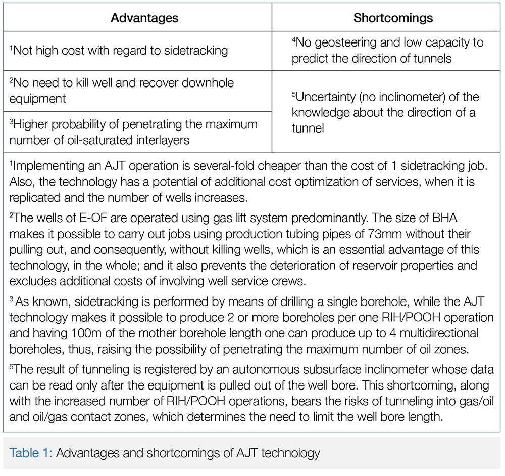
The technology has number of advantages and disadvantages (Table 1).
The run-in-hole BHA was offered by the “FracJet-Volga” LLC company.
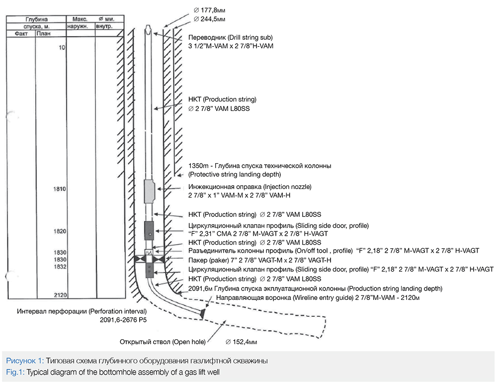
When the BHA jobs are performed, the Coiled Tubing string is run-in-hole using a production string (Fig.1). Hydrochloric acid (HCl) was used as a repressuring medium at the E-OF, in concentration of 5 to 12%.
Implementation of AJT technology
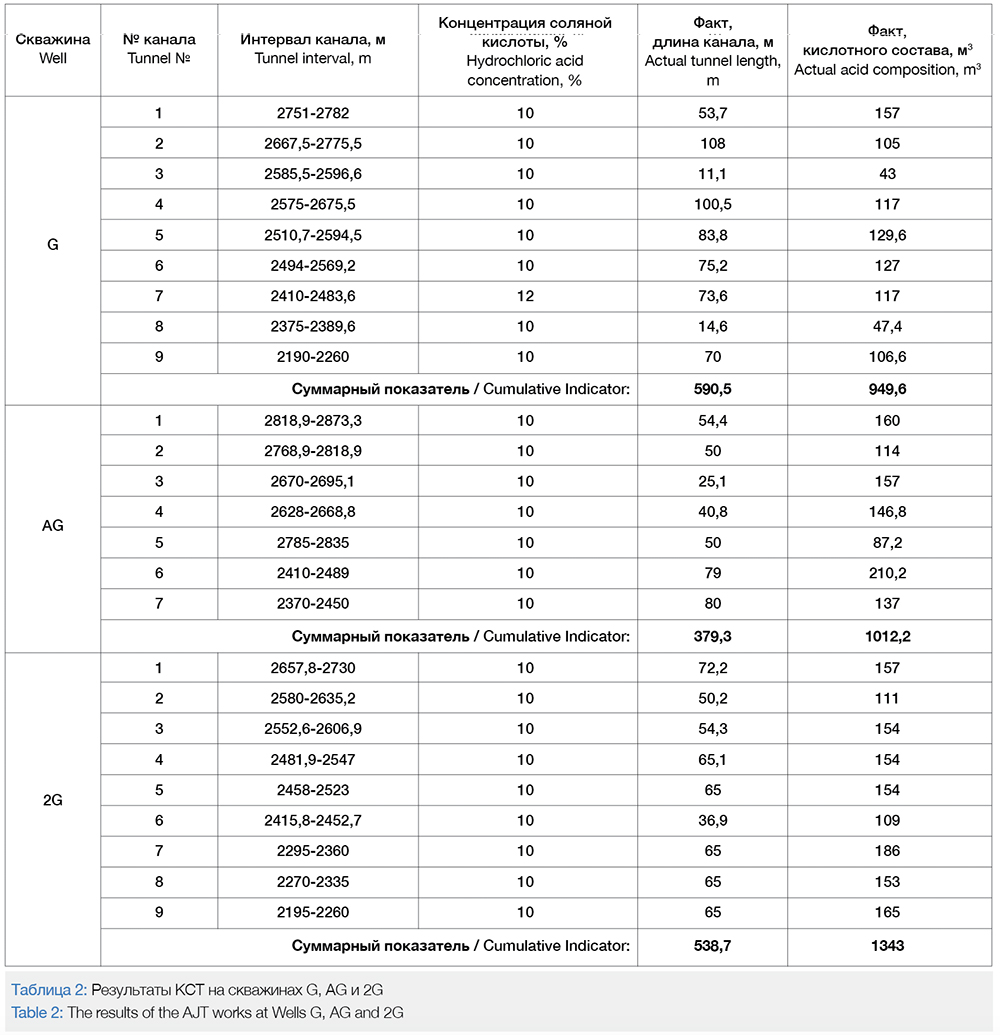
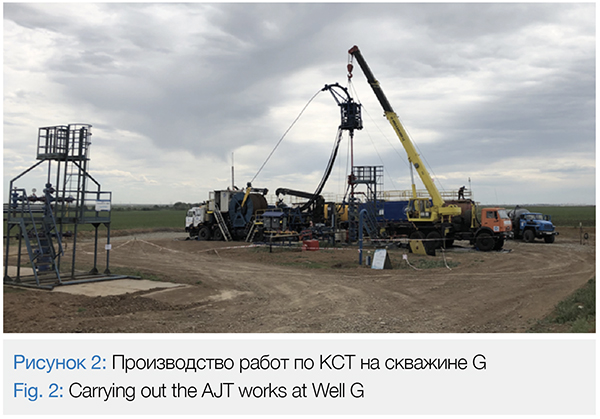
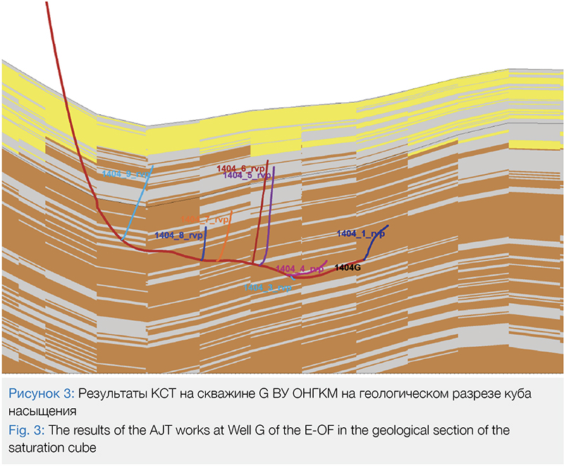
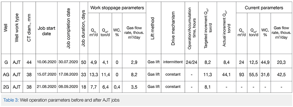
2 Horizontal wells with uncased boreholes were picked to take part in the trial. The candidate wells were featured with considerable productive formation thickness and a high degree of stratification; the well operation parameters, prior to the well intervention, are presented in Table 3. The AJT design for Well G had provisions for increasing the plugged back total depth, thus, substantiating the potential of the technology to predict the direction of subsequent tunnels. Operations at Well G made it possible to build 9 tunnels with the total length of 590.5m, the total consumption of hydrochloric acid amounted to 949.6m3 at the same time; sidetracking jobs were performed using process water as well (see Table 2). The work performance process is highlighted in Figure 2. As seen from Figure 3 all of the tunnels penetrated the overlying sublayers, however, beside the top formation zone, the bottom part of the reservoir is of pretty high geological interest. Speaking about apparent disadvantages, the following aspects of implementing the technology at Well G can be highlighted:
• High accident incidence rate of the technology – 4 cases of equipment failure (3 – BHA breakdown, 1 – BHA leaks);
• Large volume of the injected acid composition complicates and extends the period for well completion (HCl and recovering the remaining neutralized acid);
• Sidetracking is carried out upwards only, not involving the underlying sublayers;
The experience of implementing AJT technology at Well G was taken into account while carrying out the AJT works at Well AG. Additionally, a hypothesis for performing underbalanced AJT operations was tested and implemented which would enable recovering the wellbore waste (neutralized acid and rock particles), as well as enhancing the wedging effect due to the reduced formation back pressure. The underbalanced AJT wells were implemented using a gas lift system: active gas was pumped into the annulus, a manifold valve opened, and the fluid was recovered from the borehole (Figure 1). However, the recovery of the borehole fluid was temporarily stopped a tunnel washout, since the Coiled Tubing weight indication readings were actually distorted while active gas was pumped into the tubing, which made it impossible to be sure that the tunnel was really deviating from the mother borehole while the BHA stress relief was applied towards the tunnel being generated. When carrying out the underbalanced AJT works, the recovered fluid samples were analyzed, with an estimation of the hydrogen value (pH factor), density, water cut, and presence of mechanical impurities. The pH value was the key indicator; with the value of pH<3 the gas lift system operation would be stopped, with a view to prevent the oil-gathering main to corrosion. The fluid recovery would be resumed only after the fluid value would regain its parameter of pH≥3. In the whole, 7 tunnels were built at Well AG, with the total length of 379.3m, and the total consumption of hydrochloric acid of up to 1012.2m3 (Table 2).
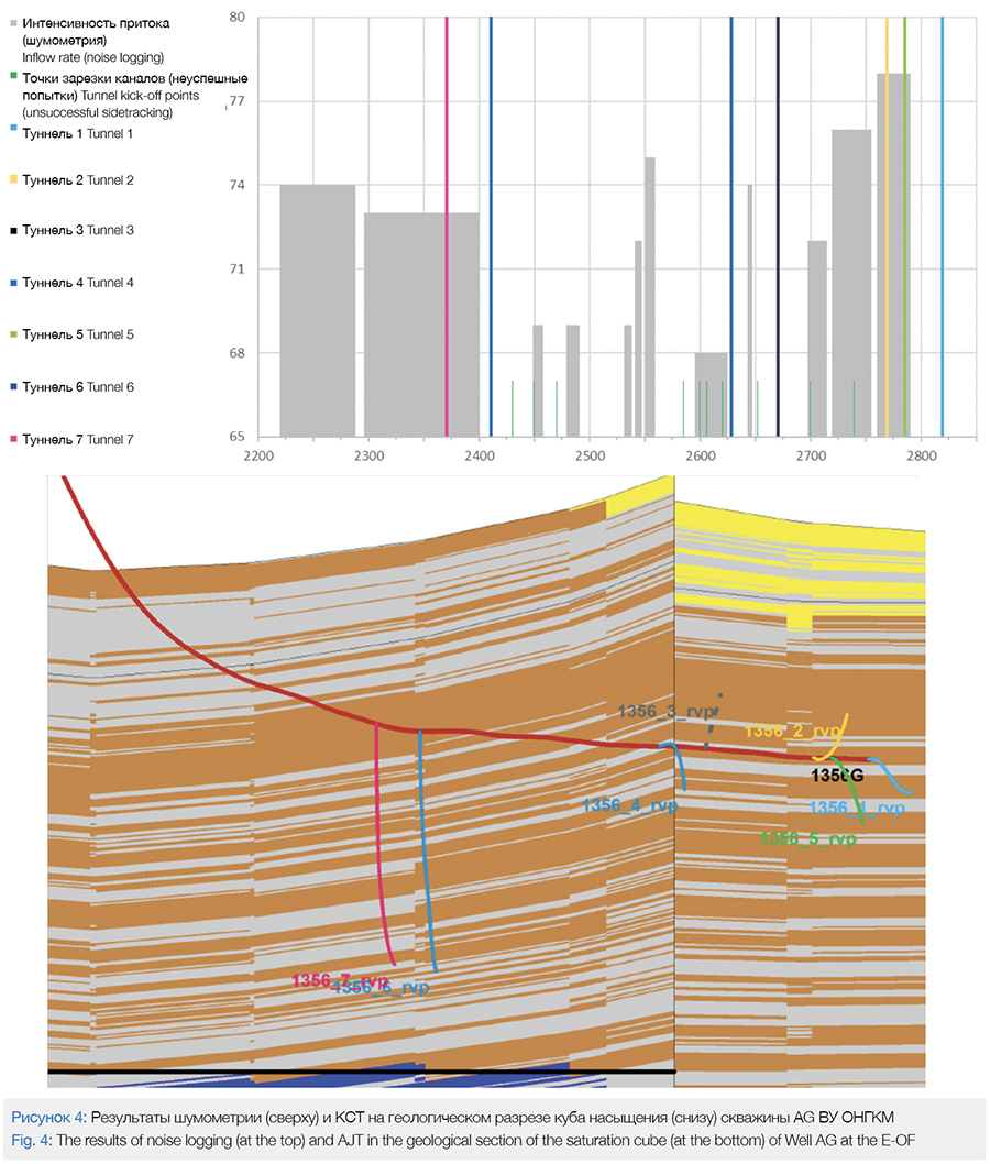
The first tunnel was built with the view to deepen the plugged back total depth. As a result of this job, the tunnels were formed towards the formation top (2 tunnels) and towards the formation bottom too (5 tunnels) (Figure 4), which allows us to speak about the success of at least one of the two hypotheses, or maybe even of the both of them:
• The 38.1mm Coiled Tubing, being a less rigid system, makes it possible to perform tunneling in both directions – towards the formation top (29%), and towards the formation bottom (71%), compared to 44.45mm Coiled Tubing; the latter makes it possible to only build tunnels directed at the top of formation (100%);
• The first tunnel, designed to extend the plugged back total depth, serves as an indicator of direction for subsequent tunnels.
The latter hypothesis was confirmed by 100% at Well G, while its convergence at Well AG was only 71%, which can be explained by special features of drilling the mother boreholes and the lithological characteristics of the wells.
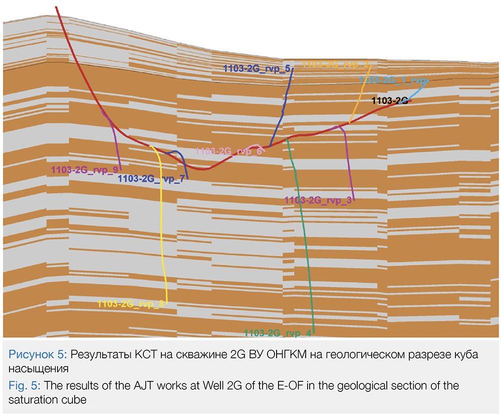
The concluding phase of the project was meant to be devoted to trying the technology’s modernization solutions at Well 2G. Overall, 9 tunnels were built, with the total length of 538.7m, and the total consumption of hydrochloric acid of up to 1343m3 (Table 3). As seen from Figure 5, a “dendritic” branching pattern was achieved, which made it possible to include into development those oil-saturated interlayers that had not been involved before. Also, it was managed to achieve the increase of the job speed from 50 to 18 days per 1 AJT operation. Noise logging was carried out after the AJT job on this well, using the results of which (Figure 4) the main inflow of the well was associated with Tunnel 7 (50%). It is supposed that Tunnel 7 has penetrated the reservoir natural fracturing area whose permeability is an order of magnitude higher than the one of the matrix rock. The contribution of Tunnels 2 and 5 has been also noticed (highlighted yellow and green in Figure 4. Some inflow of the formation fluid can be seen in the areas of previously unsuccessful sidetracking (short green columns in Figure 4), which may be a probable effect of the acid bath performed in these intervals. It is important to note that the inflow was not present at each tunnel (tunnels 3 and 6 are meant, in particular) but this phenomenon just proves “the probability of higher oil flow rate if a well has higher number of tunnels made in it”.
As for the hypotheses explaining the causes of the tunnel orientation while using the Coiled Tubing pipe, the practices of Well 2G confirmed that the azimuthal orientation was mostly achieved due to the use of less rigid (by drill pipe grade) Coiled Tubing pipe towards the top of formation: 6 of 9 boreholes formed up towards the bottom of formation (66%), although the first borehole, designed for extending plugged back total depth, was built in the direction of the top of formation, thus, confirming the unreliability of the hypothesis that the first tunnel may serve as an indicator of the direction for the rest of well tunnels.
Wells G and AG were convert to production, as part of the well stock, with flow rates of 8.4 and 44.1 ton/day, correspondingly. The values of Kprod increased from 0.12 to 0.4, and from 0.29 to 2.2, correspondingly, 752m3 or 79% of the injected volume was recovered at Well G at the moment of its turning into operation, while the volume of recovered water amounted to 869m3 or 86% at Well AG.
Conclusions and Recommendations
The following conclusions were made upon the completion of works at Wells G, AG and 2G:
1) The failure of BHA units took place as a result of axial stresses, the strength of the hydrochloric acid and hydrogen sulphide (up to 6% in the formation fluid composition), and the abrasive effect on the integrity of BHA caused by rocks in the open hole interval while performing RIH/POOH operations, which resulted in deterioration of the physical material properties (the so called, hydrogen-induced cracking and hydrogen-induced corrosion);
2) It is advisable to replace the flushing nozzles after 2 RIH/POOH jobs;
3) Due to the high rigidness of the 44.45 mm Coiled Tubing pipe, the 38.1 mm is advised to be used in the jobs, to increase the radius of the Coiled Tubing bend and the probability of bringing the underlying interlayers into the development;
4) Since no information is available regarding the trajectory of the tunnel in real-time mode, certain risks exist that tunnels might penetrate the GOC and OGC zones, which leads to the necessity of limiting tunnel length, thus, reducing the potential sweep zone Ksw; directional logging survey in real-time mode could be an optimal solution here, which would enable enhancing the technology implementation potential by involving risky candidate wells;
5) The underbalanced AJT operation has recommended itself as a light well stimulation mode;
6) The process of a gas lift system operation involves the recovery of the neutralized products when different fluid motion vectors (the recovery of neutralized products from the tubing and the pumping of HCl using Coiled Tubing string) complicate the process of sidetracking due to the fact that the weight indication data is distorted; therefore, it is advisable to stop the delivery of active gas for the periods when sidetracking takes place, shutting down the manifold valve;
7) To build tunnels in the direction of the formation bottom (downwards), which were effected by one of the two hypotheses or the synergy of the both of them (the use of less rigid Coiled Tubing pipe) and/or due to certain distinctive features of drilling the mother borehole of the well;
8) An increase the efficiency of time taken per job reduced the days required from 50 to 18 days per one job. The maximum penetrating speed, grew to 80 m/day;
9) As a result of the performed AJT jobs, the incremented oil flow rates, obtained at Wells G and AG, amounted to 8.4(+204%) and 44.1 (+386%) tons/day, Kprod increased from 0.12 to 0.4 and from 0.29 to 2.2, correspondingly.
10) The technology has a great potential and can be actively used for extending the free-flow production period of a well without involving workover crews and it can be also applied at gas lift oil and gas wells operated with artificial lift with participation of workover crews.
The team of the authors expresses their thanks to the «FracJet-Volga” LLC company for carrying out the works, to “Gasprom Neft Orenburg” and the”Research and Development Center” LLC (NTC) for their all-out support in the implementation of the “Acid Jet Tunneling Using Coiled Tubing” technology which was implemented for the first time within the boundaries of “Gasprom Neft” PJSC”.
References
1 The Engineering Design of the Development of the Eastern Part of the Orenburg Oil and Gas Condensate Field in the Orenburg Region / “TANDEM” JSC”.
2 D.V. Novokreshchennykh, A.V. Raspopov. The Prospects for Development of the Radial Drilling Technologies at the Fields of the Perm Territory // «Neftyanoye Khozyaistvo» (Oil Industry) magazine – 2014 – Issue 3 – pp.54-57.
3 The Efficiency of Implementing the Technology of Radial Drilling and Matrix Acidizing of the Carbonate Reservoirs at the Fields of the Perm Territory / D.V.Novokreshchennykh, A.V.Raspopov // «Neftepromyslovoye Delo»(Oil Field Engineering) – 2016 – Issue 4 – pp.118-121.
4 Stanley F.O. Global application of coiled-tubing acid tunneling yields effective carbonate stimulation / F.O. Stanley, L.N. Portman, J.D. Diaz, R. Leonard Darmawan, J.P. Strasberg, J.S. Clark, M.S. Navarro // SPE Annual Technical Conference and Exhibition held in Florence, Italy, 19-22September 2010. – SPE 135604.
Authors:
Konstantin Y. Kyzyma, Gazprom Neft Orenburg LLC,
Vadim Y.Khoryushin, Gazprom Neft Orenburg LLC,
Sergey M. Simakov, Gazprom Neft NTC LLC,
Vadim S. Devyatkin Gazprom Neft NTC LLC,
Artur R. Khusnutdinov Gazprom Neft NTC LLC,
Pavel N. Gerasimenko Gazprom Neft NTC LLC,
Alexander A. Kundik Gazprom Neft Orenburg LLC

