Gazprom Neft: LWD Applications in the Construction of Horizontal Wells

Introduction
Horizontal well construction is an effective method of developing oil and gas fields with a complex structure [1]. Currently, 77% of Gazprom Neft wells under construction use the standard set of Formation Evaluation (FE) methods. These include resistivity logging (RL) and gamma ray logging (GR) (GOST 32358-2013). The application of the FE method presents certain difficulties in distinguishing reservoirs and resolving geosteeing problems. In addition, there is a potential risk of drilling a well in a reservoir with low filtration-volume properties or in low-permeability rocks.
Selecting the Optimal LWD Tool.
LWD Matrix
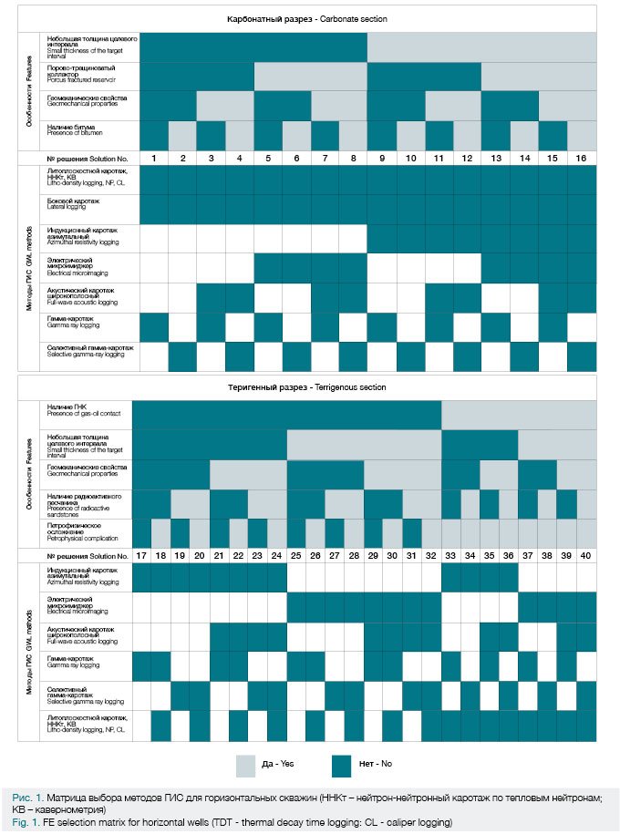
In order to facilitate an analysis of the current situation, the geological features of carbonate and terrigenous sections were systematized. Logical schemes were developed for each type of section, and a tool for selecting the optimal FE method has been proposed.
Consideration was given only to logging while drilling (LWD); and the carbonate section was classified by the presence of the next attributes: low target interval thickness; porous and fractured reservoir; the existence of bitumen in the pore space; and the requirement to monitor borehole condition. For the terrigenous section the following features are typical: the presence of gas-oil contact; low target interval thickness; the existence of radioactive sandstone; the indeterminate nature of petro-physical data interpretation; and the requirement to monitor the borehole condition.
The best FE method was chosen in the following manner. Individual FE methods were distinguished, each of which was associated with one specific feature of the section [2] in terms of sensitivity.
The logical connections between the methods and features were systematically presented in the form of a logic scheme or «decision tree». This approach allowed consistent verification of the existence of geological features typical of each type of section. Moreover, the indeterminate nature of petro-physical interpretation suggests that there are cases when induction logging and gamma logging are not sufficient to isolate reservoirs. However, the terrigenous section under examination reveals neither gas-oil contact nor radioactive sand stone and does not require monitoring of the borehole condition.
Using the «decision tree», an approach was developed that utilizes the LWD matrix as a tool for choosing FE methods for logging while drilling (Fig. 1).
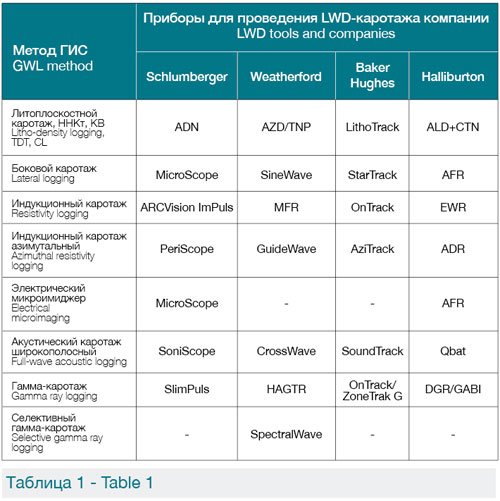
An analysis was conducted of the market of oilfield services organizations which provide extended logging services when drilling in the Russian Federation. The available LWD tools were systematized and their specific names indicated [3]. These tools are designed for wells with a diameter of 4 ¾ «(121 mm) or more. Table 1 shows the classification of currently existing LWD tools and methods. This classification is an additional result of creating the common LWD matrix.
In addition to the type of LWD tool used, well drilling efficiency can be influenced by the tools being positioned in a single cluster. Regarding geosteeing, LWD sensors must be positioned in relation to the drill string bottom hole assembly (BHA) – i.e. the distance from the logging tool to the bottom hole. Let us consider a model example showing the influence of this distance on the efficiency of geo-navigation.
A critical element is the ability to be able promptly to return to the pay zone (reservoir). Also bore length in a low-permeability rock area can influence horizontal well construction efficiency.
We will create a model situation of BHA output from the target area. It will comply with conditions of maximum spatial borehole inclination, angle of borehole attack into the target formation, and the distance from the drill bit to the sensor. We shall specify the possible angles of intersection of the formation roof with the borehole. This will be in the interval between 1° and 5° (if the angle is any greater, the viability of continued drilling would require further analysis and is quite often ineffective). In the case of Gazprom Neft assets, the most common maximum permissible inclination β is 1.5° for 10 m. We shall assume this value as the upper limit. The distance from the drill bit to LWD sensor (non-measured zone) is x = 3-15 m.
We shall assume that the formation roof boundary intersects the wellbore at an angle of α. In this case, until the moment that the tool’s geosteeing sensor exits the formation, any information concerning borehole intersection with the formation boundary will not be recorded. Let us assume then that the bottom hole signal is propagated instantly, and that the relevant information is interpreted by specialists immediately (log data is clearly differentiated in terms of the values presented by the formation and roof). In this case, the BHA will exit the formation at offset (unmeasured) distance of x. It is at this moment that the zenith angle of the borehole trajectory begins to decrease before return to the formation. The following formula can be used to assess the length of the well outside the reservoir: sum of segments b + c + c + b.
By virtue of situational symmetry and small angles: cos1° ≈ cos5° ≈ 1, b ≈ x, c = α / β.
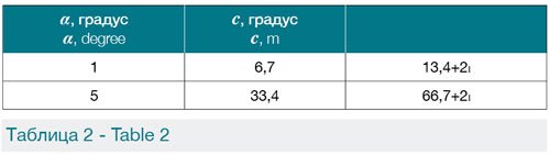
Refer to Table 2 for the results of calculating the distance c and the length of the well outside the reservoir.
Thus, the size of the offset (unmeasured) area significantly affects the length of the well outside the reservoir. Thus, for the offset (unmeasured) area x = 3 m and the intersection angle α = 1°. The length of the well outside the reservoir is 19.4 m, while for x = 15 m the length increases to 44 m (more than 2 times). A similar situation is observed for the worst scenario with an angle of intersection α = 5°: 72.7 and 96.8 m correspondingly. However, it should be noted that the difference in the lengths of the wells outside the reservoir is reduced.
At an angle of intersection α = 6°, the minimum possible length is 86 m, while at an angle α = 7°, it comes to 100 m. This indicates an approximate loss of 10% of length for a well with a horizontal section 1000 m in the case of a single exit from the reservoir. Therefore, in the case of a large reservoir intersection angle, it is recommended that the well be re-drilled, cutting off the current well bore in the reservoir interval.
The results obtained using an estimation method based on sensor location geometry and formation thickness and inclination angles can also be used to determine the predictive efficiency of drilling the horizontal section of the well. This will both obviate overstating planned performance indicators and justify more proactive geosteeing methods for achieving maximum efficiency.
Preconditions for the Introduction of the LWD Matrix
As an illustration of the viability of promoting the use of the LWD matrix, the selection of the expanded LWD method has led to increase in the drilling efficiency of horizontal wells in a number of fields. At the Sugmutskoye field, the extended FE method was applied to a horizontal well drilled into the BS9-2 formation after drilling (Fig. 2). This demonstrated an overestimation of penetration efficiency when using the standard set of FE methods in the drilling process. In this case, the use of additional methods allowed for the effective length of the well to be determined, possibly influencing well trajectory. A significant change in porosity with virtually constant gamma logging values can be noted. This renders it impossible to use gamma logging results in this formation for the purpose of geosteeing.
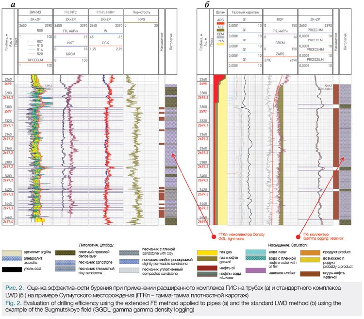
Given a horizontal section length of 204m, drilling efficiency using the limited LWD method was 100%, while the extended FE method applied to pipes produced 46%.
In the case of the Messoyakhskoye field (Fig. 3) there are areas of increased radioactivity in the reservoir zones. These may affect the well-drilling strategy. In this case, the use of the extended FE method in the drilling process including neutron and density methods is recommended. This will either confirm or refute reservoir existence in areas of high radioactivity.
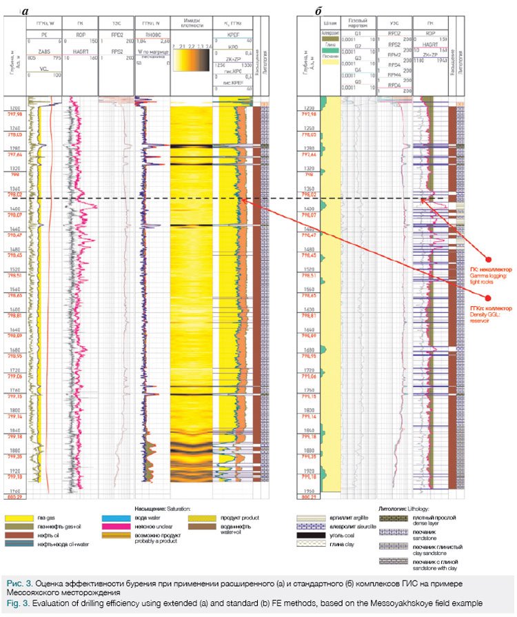
Drilling efficiency using the standard FE complex and extended FE method was 87% and 94%, respectively.
At the Tsarichanskoye field, due to its complex mineralogy and the secondary rock transformations constituting the reservoir, the application of a standard logging method is not recommended. When drilling a well based on gamma logging data, complex mineral composition does not allow accurate estimation of the production interval. It may even lead to the mistaken decision not to correct well trajectory after a depth of 4200m, but rather to drill horizontally even though GGLD data suggests that the reservoir lies at other depths (Fig. 4). In this case, density logging is allowed for increased penetration and for the predicted production rate to be achieved.
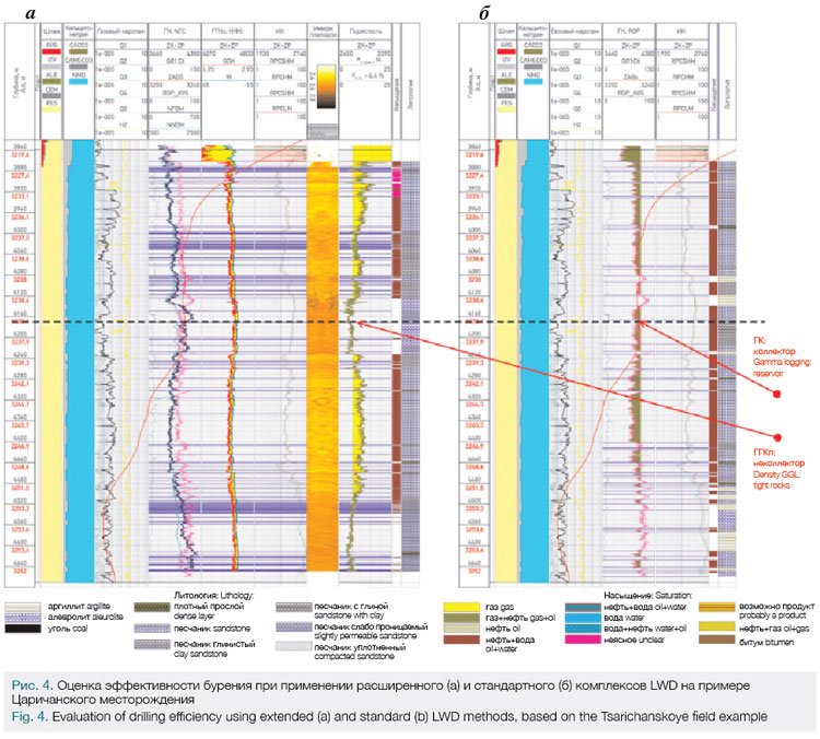
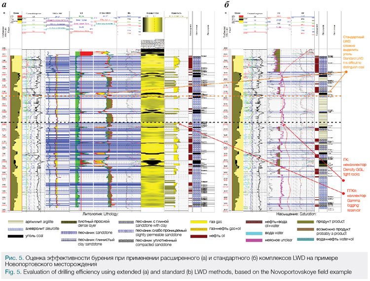
Drilling efficiency using the standard LWD method and the expanded LWD complex was 77% and 66%, respectively. Intervals of carbonized and highly radioactive deposits in the Jurassic layers of the Novoportovskoye field need to be noted. Based on standard logging data, these are related correspondingly to reservoirs and low-permeability rocks. Thus in the aims of timely decision-making in the well geosteeing process, it was decided to use the extended FE method, allowing for optimal assessment of productive areas (Fig. 5). Drilling efficiency using the standard LWD method and extended LWD method was 31% and
45%, respectively.
In wells which presume the use of hydraulic fracturing, an acoustic caliper or a calculated cavernous index must be employed for the purpose of accurately interpreting the results and selecting optimal zones for positioning multi-stage hydraulic fracturing equipment.
Conclusions
The authors would like to place on record their thanks to all the specialists from the GeoNavigator Drilling Management Center who participated in the collection and processing of the data, especially the contributions from the Petrophysicists V.I. Pastukh and A.Yu. Ignatov, whose input was critical to the decision making process.
The LWD matrix tool proposed herein does not represent a panacea in determining the requisite set of methods, nor does it exclude the need to analyze the available geological information relating to section and lateral properties of a formation. However, it does allow for the selection of LWD methods to be automated and facilitates primary classification.
Given the requisite geological and petro-physical information, the LWD matrix allows for existing logging methods to be taken into account by service companies in their technical operations, while offering promising directions for the development of new LWD tools. Furthermore, the importance of positioning LWD sensors relative to the BHA bit should always be considered.
References
1. Pavlov E., Mazitov M., Moor N. Logging while drilling: Use of LWD on the example of JV1 formation of Urevskoye field // Neftegazovaya vertikal. – 2011. – No. 2. – p. 74–77.
2. Dakhnov V.N. Interpretation of the results of geophysical investigations of well sections. Moscow: Nedra, 1982.-448 p.
3. http://www.slb.com/; https://www.weatherford.com/; http://www.halliburton.com https://www.bakerhughes.com
Published with thanks to Gazprom Neft & PROneft Magazine
Материал любезно предоставлен компанией ПАО «Газпром нефть» и журналом «PROнефть».
A.V. Bilinchuk, A.R. Listik
Gazprom Neft PJSC, Russia, Saint-Petersburg
V.A. Kindyuk, P.S. Arzumanyan
Gazprom Neft NTC LLC, Russia, Saint-Petersburg