Gazpromneft NTC: Coiled Tubing For the Future
Coiled tubing (CT) is a technology first invented during World War II for laying a fuel pipeline under water (Operation Pluto), but it was not until the late 1980’s that it came into common use. Well cleanout, nitrogen lifting, dissolving of hydrate and paraffin plugs and many other operations involving CT have now become standard fare. Today, coiled tubing units conduct nearly all types of well workover (WWO) operations; they are fully automated and are, in fact, nothing short of pilot models for drilling and workover rigs of the future. Western Siberia, is Russia’s number one oil and gas province, can rightfully be considered its main proving ground where new technologies are being tested and implemented, and it also beats all other regions in terms of concentration of CT systems per unit area. It is in this region that numerous CT technologies, such as geophysical well logging, sand-jet perforation, milling of multistage hydraulic fracturing (MSHF) ports and activating them using specialized bottom-hole assemblies, etc., have found their application.
Each year, more and more reserves are classified as hard to recover due to structure complexity, depth of occurrence, or accessibility, so standard well operations are no longer fit to address the challenges that oil producers must face today. The problem of drilling more complex wells, however, spells the need for development and use of non-standard equipment. Here, we are talking about MSHF completion systems with CT as being the main tool that meets modern requirements.
Statistics for CT use in Gazprom Neft PJSC show the following CT lengths used: 4000 m in 2010–2015, 4500 m in 2016, 5000 m in 2017, the current trend being towards greater lengths and greater diameters. Along with the length, the CT wall thickness has also changed as tapered CT strings (i. e. those with non-uniform wall thickness optimized for specific downhole conditions) came into use.
Such changes in length and diameter have triggered a number of changes in the technical characteristics of the equipment, such as the pull capacity of the power pack injector, the diameter of the reel assembly and its overall dimensions.
USING CT TO ADDRESS CURRENT CHALLENGES
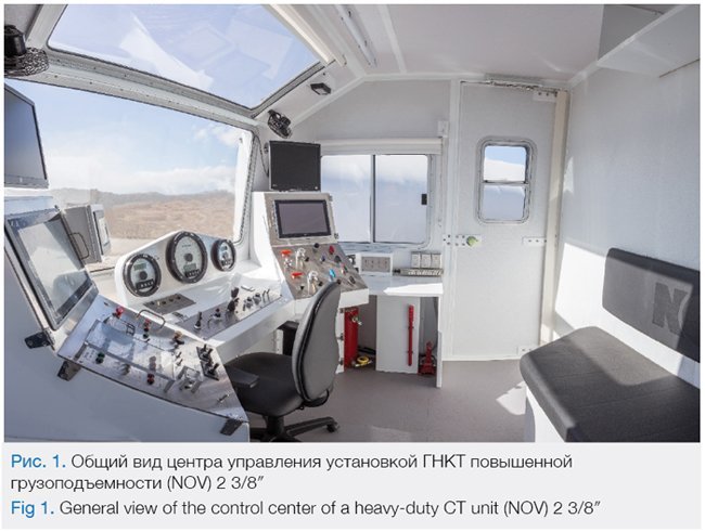
The use of CT makes it possible to address technological challenges that until today were considered difficult to manage. A few years ago, horizontal well section lengths stood at around 500–700m, while now they reach 2000– 3000m, the measured depth (MD) being 6100–6500m and upward. One specific set of challenges, that deserves a separate mention, are problems that arise in connection with the development of territories and fields beyond the Arctic Circle. Here, the key factors are low temperatures and limited hydraulic characteristics of most manufacturer’s CT systems. At -35°C, the existing equipment fails to meet the requirements imposed on it from both technical and technological points of view. In such conditions, a solution is found with heavy-duty CT units (see Fig. 1).
A heavy-duty CT unit with a reel capacity of 6500 m and CT diameter of 2 3/8′′ (60.3 mm) can be used:
- to control full-bore MSHF sleeves on horizontal sections of 2000 m and more, where an additional load of more than 10 kN is required;
- in controlled drilling, where the telemetry system includes a high-power electric orienting tool capable of rotating the downhole positive displacement motor ( PDM) around its axis, and where the resulting steering angle can create a drilling window of 1 m;
- in complex wells that require the use of tapering technology.
It is obvious that operations involving CT strings with a diameter of 60 mm at depths greater than 6000 m cannot be accomplished without a power pack with a guaranteed safety margin on top of the injector
head’s design pull capacity. There are some western companies that manufacture injector heads with electric drives, which make it possible to:
- increase the pull capacity of the system;
- provide independence from temperature conditions;
- provide a manifold increase in RIH/POOH speeds;
- improve steerability.
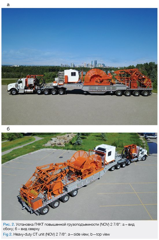
A CT unit with a reel capacity of 6500 m and a CT diameter of 2 7/8′′ (73.0 mm) (see Fig. 2) can be used to accomplish MSHF through a CT string, which provides a clear advantage in terms of the speed of interstage transitioning and the volume of injected fluid. There is no need to fill the CT string before the start of the HF operation and during the flush stage. We would also like to highlight the unique opportunity of using a CT string for multi-stage re-fracturing operations in wells with open ports, where the HF fluid is targeted through a specific port just the same way as it would be in the case of selective opening/closing of ports.
In this case, the distance between the MSHF ports may constitute a limiting factor, but in Western Siberia, where that distance varies from 50 to 100 m, this is not critical. It is fair to assume that, in the case of uncemented ports, each subsequent MSHF stage may bring about fluid leaks through fractures that have formed earlier. It should be noted that, when selecting a candidate well for MSHF operations involving CT strings with a diameter of 2 7/8′′, the frac fluid flow rate and the injection pressure should be taken into account.
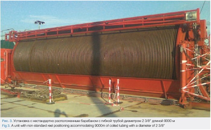
In situations similar to those described above, a reel assembly accommodating a CT length of 6500 m can be transported on board a separate lowboy semi- trailer; however, there are CT units with non-standard reel positioning relative to the trailer axis. Fig. 3 shows a reel accommodating 9000 m of coiled tubing with a diameter of 2 3/8′′ (60.3 mm).
Apart from the advantages we have we have mentioned, the CT units in question have two disadvantages: high cost and large weight. The former makes your project more expensive, and the latter calls for special permits to be obtained for OOG load transportation. There is, thus, an opportunity for service companies to think about step-by-step introduction of large-sized CT strings where the service cost will tend to reduce thanks to the large number of wells covered by the offering and the lowered transportation costs involved in CT delivery.
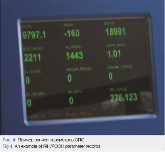
People often ask whether there are specific standards governing the duration of a particular operation. Well, there are, and can be, no such standards, but there are speed limits prescribed for RIH/POOH operations on CT strings. Today, any RIH/POOH operations on a CT string, regardless of its diameter, progress at a rate of 15–20 m/min in a vertical section and 5–10 m/ min in a horizontal section. Since the RIH/POOH time increases with depth, comprising on average about 40% of the total productive time, this means that, if we want to drill deeper wells, we should offset the time losses due to increased depth by increasing the RIH/POOH speed at least 2 times. In North America, RIH/POOH speeds have long exceeded 50 m/min. Fig. 4 shows a monitor used to record the working parameters of an initial RIH operation that progresses with a speed greater than 160 ft/min (48.7 m/min).
Another aspect that deserves attention is the road surface quality to Russian fields. It is no secret that access roads to and across Russian oil and gas fields are inferior to western ones in terms of surfacing quality, which is why vehicle manufacturers tend to supply off-road versions to the industry. Among the factors affecting a vehicle’s off-road capability in Western Siberia, where 6×6 all-terrain wheelbase is used, is the length of the bearing frame. The experience acquired using this equipment in a variety of settings, including the loose sands of Western Siberia and the impassable muds of Orenburg region, shows that short units have a certain advantage over their counterparts with trailers.
Certain process-specific differences between CT and HF operations affect the design features of the respective equipment applied, but there are also similar points, such as the long-time personnel presence in the computerized control center (Data Van in the case of HF) of each respective operation. Here, it may be worth paying attention to whether there is potential for increasing the working space in the operator’s cabin, because modern high-tech operations tend to have control and supervision functions that the operator alone cannot handle, so other onsite personnel must also be present. Meanwhile, collaborative response times to be observed by those persons in varius situations should be reduced.
Tasks are assigned not only to service companies in charge of CT maintenance, but also to equipment manufacturers. Solutions should be found based on requests from oil producing companies, which, in turn, are governed by their investigations into optimal techniques for hydrocarbon recovery in the face of the deteriorating reserves structure.
Our vision for a CT unit of the future is that of a multifunctional complex capable of handling process- specific tasks and adjusting workflows in real time. Possible solutions can vary from conventional to high- tech, which is also true for possible configurations of the system to be used for preventing equipment failures due to low pressure in the system or changes in the wall thickness or shape of the CT string.
CONCLUSION
The technology solutions described in this article can be implemented in Gazprom Neft PJSC in terms of both project equipment and techniques for its use. The methods and approaches that have been developed towards the implementation of new projects involving CT systems are a capable tool to help you find forward-looking solutions for your problems and devise actionable algorithms for the near future. The technical overview of equipment and technologies set forth above makes it possible, even today, to minimize future risks and production unit costs, as well as to take early action to systemize your work with potential contractors with a detailed approach, disclosing the applicable technical criteria and making your selection based on the actual equipment, logistics, and timing requirements, which is very important when relocating non-standard equipment from other regions and foreign countries.
BIBLIOGRAPHY
1. SPE/ICoTA Coiled Tubing and Well Intervention Conference and Exibition 27-28 Mar 2018. The Woodlands Waterway Marriot Hotel & Convention Center. The Woodlands, Texas, USA
2. Hydraulic Fracture Placement Assessment in a Fiber Optic Compatible Coiled Tubing Activated Cemented Single Point Entry System / A. Gustavo [et al.] // SPE- 189842-MS. – 2018.
3. Колтюбинг повышает эффективность мультистадийных гидроразрывов на Новопортовском месторождении / А.В. Белов [и др.] (Coil tubing improves the efficiency of multi-stage hydraulic fracturing operation at the Novoportovskoye field / A. V. Belov [et al.]) // SPE-187715-RU – 2017.
Article authored by:
S. M. Simakov
Gazpromneft Science and Technology Centre (Gazpromneft NTC, LLC)
Published with thanks to Gazprom Neft & PROneft Magazine


