Gazpromneft NTC: Developing Inhouse 3D Hydrofracturing Models
This paper provides an analytical solution for the Pseudo3D model for hydrofracturing in a simplified geomechanical setting. The problem is solved in dimensionless parameters to ensure the universality of the solution. Dimensional lengths on height are plotted.
The obtained solution allows to quickly find the geometry of the fracture during the development, as well as to estimate the required volume of fluid injection to achieve the desired fracture length, including for hybrid hydrofracturing with several fluids.
Introduction
Hydrofracturing is the basic method to stimulate oil production in conventional and unconventional reservoirs. Customized software packages are used for planning, support and optimization of hydrofracturing operations. For example, software packages MFrac, FracPro, FracCADE, Mangrove are either sold to operators and oilfield service companies or represent in-house products of the oilfield service companies, and calculations made using the packages are only provided as a part of the services. All hydrofracturing run on the assets of Gazprom Neft PJSC are imported ones, and it is highly difficult to purchase licenses (services) for them due to sanctions. Therefore, the development of own solutions to hydrofracturing design simulation is one of the top-priority tasks of the branch within the framework of the import substitution strategy.
Basic analytical solutions (PKN, KGD, Radial) in the hydrofracturing theory were developed in 50-70s of the twentieth century. The PKN model [1,2] is the one of these three models that suits the fields in Western Siberia the best. Still, even this model does not cover the geological section structure. To take that into account, the development of such numerical models as Pseudo3D, Planar3D and Full3D, demanding high computing power was initiated. Besides, this paper puts a focus on obtaining of proxy and analytical solution in the Pseudo3D setting.
Assumptions of Pseudo-3D Model
The Assumptions model [3,4] (see Fig. 1) actually represents an extension of the PKN model, and it is based on the following assumptions:
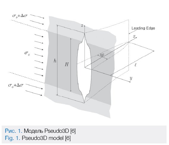
1) A fracture is developing within the plane oriented at the right angle to the minimum rock stress that has a horizontal direction at higher depths. The fracture grows in size symmetrically to the right and to the left, that’s why only one fracture wing is plotted in many simulators. Our model also features a symmetry in the vertical plane.
2) For the models describing a hydraulic fracture a so called net pressure p=pf– σ0 is introduced, where pf is total fluid pressure and σ0 is rock pressure in the reservoir. At the edge of the fracture with half-length L opening of the fracture makes w=0, and from elastic fracture mechanics equations it follows that p(L)=0. The fracture border itself is defined by two functions L(t) and h(x,t)). In the formula below these functions are substituted with L(h0) and h(x, h0) as in out setting any time t corresponds to unique value h0 – fracture height in the center, consequently the time itself may be expressed as t(h0).
3) The vertical fluid flow is considered negligible as compared to the horizontal fluid flow. That is the case when the fracture mainly grows in the horizontal plane. The law of conservation of mass is applied to every vertical section, while the horizontal flow is averaged in the vertical plane.
4) Fracture opening in each profile depends on plane-strain conditions. This approximation follows from the basic assumption h≪ L. Still, on the fracture tip this approximation has no effect as well.
5) Leaks to a reservoir are calculated by the Carter formula based on the assumption of one-dimensional flow next to the fracture periphery.
Mathematical Setting
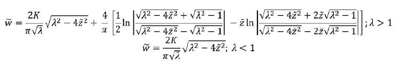
On the basis of flat elasticity theory [5] the below formula is derived for the profile of a fracture with height h with producing reservoir having thickness H, stress contrast ∆σ and toughness of adjacent layers KI, Young’s modulus E, and Poison’s ratio ν:
Dimensionless parameters are introduced here [6]:
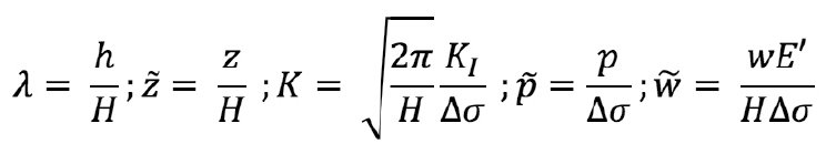
Here E’=  is plane strain modulus. In the dimensionless form the fracture profile only depends on dimensionless fracture toughness K, which as a rule is rather low in reservoir conditions and has a little effect on fracture opening, and on dimensionless height λ.
In the same manner, the Poiseuille equation is derived for the one-dimensional flow in the fracture:
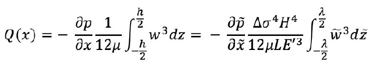
The basic equation for fracture development is the law of conservation of mass for one-dimensional flow:
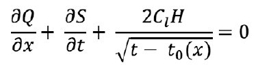
where, Cl is leakage factor according to the Carter formula, and S is cross-sectional area of the fracture vertical profile.
Proxy Model Building
The fundamental idea for proxy model building consists in abandonment of numerical solution through development of difference schemes same as in the conventional Cell-based Pseudo3D approach [6]. It is suggested using the known analytical solutions instead, and cross linking those solutions. For example, the authors of paper [7] suggest using the accurate analytical solution to calculate the width profile by height, the Irwin criterion to calculate height, the PKN solution to calculate length, and cross linking on the basis of net pressure as opposed to the previous papers, for example [8], where an incorrect approximation was used to calculate net pressure, and cross linking was done with reference to the height value.
Obtaining of Analytical Solution
It is now possible to obtain an approximate analytical solution due to derivation of new dimensionless parameters missing in [6], namely:
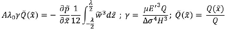
Where, A(h0)=  is a half aspect ratio of a fracture,
and γ=  is a small parameter of the mathematical problem, and expansion with respect to that parameter makes it possible to obtain a new analytical solution of the problem.
The physical meaning of parameter γ is the ratio of reservoir thickness and characteristic obtainable fracture length. The lower γ, the longer the fracture is.
For further problem solution dimensionless permeability of fracture is derived as
To derive dimensionless parameters, nondimensionalized time is to be calculated as follows:
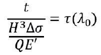
and the following equation is obtained:
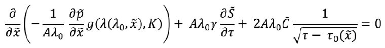
It is supplemented by the boundary condition of flow to the right half in the fracture origin:
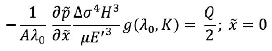
Or:
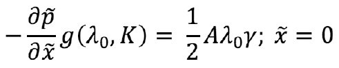
The dimensionless leakage parameter being low for most fractures has been derived here. It should be noted that this is a parameter related to the shape dependant on leakage rate, an «instant» leakage parameter. The «integral» leakage parameter is as a rule several orders higher. This parameter characterizes exactly fluid efficiency and total volume of a fracture but not its shape.
To obtain an analytical solution, one should omit all terms in the equation containing small parameters. Thereupon, the following equation is obtained with account of the boundary condition:
![]()
The equation indicates the continuous flow of fluid along the fracture, i.e. outflows in the vertical plane are negligible. This is exactly the basic provision of the Pseudo3D model.
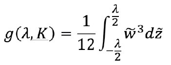
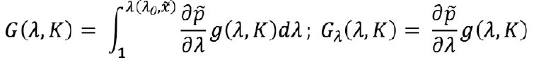
On integrating the equation in parts, we obtain the following ratio in quadratures:
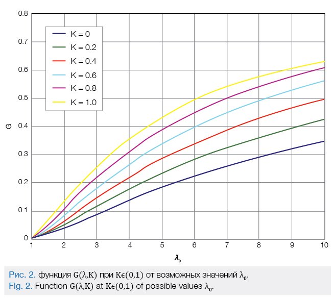
Where, G(λ0,K) is a universal function which characterizes the obtainable nondimensionalized fracture length for the given height.
Its graphs related to various values of parameter Kϵ(0,1) are given below:
Fracture half-length L is calculated by the formula:
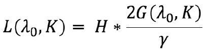
From the above formula it follows that the derived dimensionless parameter γ is the only parameter which depends on the hydrofracturing design and may affect fracture length.
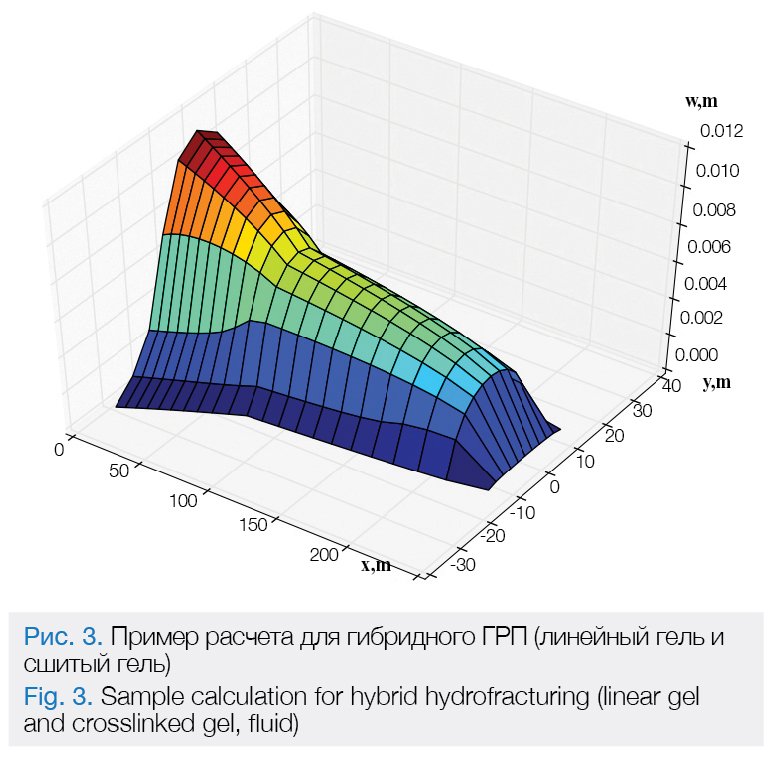
This approximate solution for continuous flow makes it possible to obtain a fracture shape not only for any hydrofracturing gel but for the fracture created using different hydrofracturing gels applied one-by-one. The sample calculation for hybrid hydrofracturing is shown in Fig. 3.
Conclusions
The paper gives the basic approaches to hydrofracturing simulation in the Pseudo3D setting.
The main advantage of proxy and approximate analytical solution is that it is not necessary to build a numerical solution of a second-order non-linear equation.
Also, it should be noted that the analytical solution is based on dimensionless variables and depends on three dimensionless parameters which allows to determine the degree of formation lithology and fluid rheology impact on obtainable values of the hydraulic fracture geometry. Besides, the specific feature of this solution is the principal possibility to simulate the
hybrid hydrofracturing.
Shel Egor Vladimirovich, Paderin Grigory Vladimirovich
(LLC Gazpromneft Science & Technology Center)