Horses & Zebras: Right Sizing Technology for the Oilfield

A major new East Siberian oilfield development program with a multi-rig/multi-lateral drilling program was well underway, when an increasingly difficult fluid loss issue began to evolve within the principal pay-zone. The combination of multiple-rigs (> 10), with multi-laterals longer than 6,000m in the pay-zone in each well, with a large areal field and reservoir footprint was increasingly being drilled in tighter/poorer rock which meant that the fluid loss was becoming a major economic issue. The conventional approaches to solve the issue had been exhausted, which finally lead to the use of multiple and extensive cement-plugs being placed in the reservoir. Anyone who knows anything about the oilfield would readily admit that when you start pumping cement plugs as a fluid-loss additive within the pay-zone, that this cannot be a good solution or outcome.
The losses were resulting in millions of dollars of costs, related to Non-Productive Time (NPT), pill and mud-costs, on an annual basis, across a number of rig-lines. Up to 20 cement plugs were being placed, to enable the wells to be drilled to the planned TD, this approach was simply not sustainable. Additionally, as the well stock was increasingly being placed in poorer quality rock, the formation damage resulting from the losses and the supposed cement plug solution was extremely impactful. The final nail in the coffin was the fact that even with this extreme solution of setting cement plugs, the planned reservoir metreage was progressively being underdelivered. From 2018, 2019 and 2020, the total reservoir metreage drilled dropped by 10,000m, 20,000m and 30,000m respectively; clearly a trend that could not continue. As well as the lack of the resulting productivity, the reduction in the planned multi-laterals, was creating undrained areas of the main field that would never be able to be effectively or economically re-developed in the future, in anyway.
Engineering Approach
As an engineering challenge, there are many different approaches to solve this problem, but to ensure that the most effective solution was applied, a return to basic well construction principles was required. This was key, because within engineering technical staff, there can be an inherent bias to want to work with interesting, technically advanced, challenging and complex solutions; regardless of their merit.
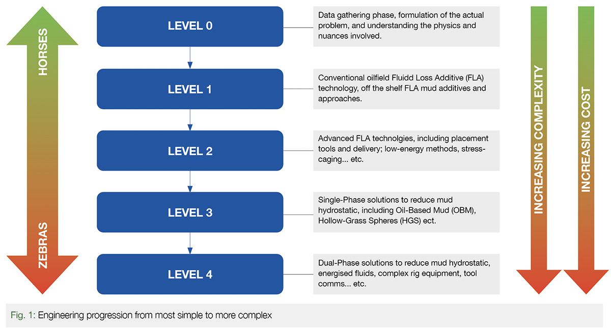
As the idiom states, “When you hear hoofbeats, think horses, not zebras” is most appropriate. This means that the mostly likely solution is the simplest one, not because simpler explanations are more correct, but because you make fewer assumptions when looking for horses instead of zebras. As we saw, while there were more costly, complex and indeed riskier solutions from a safety perspective; a progression of consideration from the simplistic to the complex (See Fig. 1.) resulted in the direct selection of a much more effective solution that paid off in many more ways than had been originally imagined. In many cases, the temptation is to jump straight from Level 0 to Level 4, as was the case with the discussion in this article.
Data Gathering and Continuous Learning (Level 0)
The progression in drilling improvement had been underway since the original Development drilling operations had begun in 2015, and in the initial stages (LEVEL 0), conventional oilfield drilling data gathering had been occurring (Aliyev et al., 2017). At this time, in the higher permeability Southern section of the field, where drilling was concentrated, the losses occurred but were more typically intermittent. Additionally, most of the drilling was simple horizontals with limited reservoir exposure (750 – 1,000 m per well). Even so, the nature of the losses had been well classified and as the multi-lateral program was initiated; further evidence was collected and presented which indicated that there were in fact measurable directional features within the reservoir which were associated with the losses (Rylance et al., 2018) and (Rylance et al., 2020). Furthermore, extensive evidence had been gathered that identified) that a threshold loss initiation pressure existed at a certain Effective Circulating Density (ECD) which appeared to be ubiquitous. As the drilling program progressed, continuous and cumulative evidence was gathered for this, through the drilling operations themselves and additional potential measurements were collected, such as eXtended Leak-Off Testing (XLOT) in wells with high-angle pilot holes.
Conventional Fluid-Loss Approaches (Level 1)
As the drilling program progressed, the drilling engineering Team set themselves up for success, by managing (LEVEL 1) aspects, to be able to treat, manage and measure the increasing fluid-loss occurrences during drilling operations (Aliyev et al., 2017). This preparation included ensuring access to the conventional suite of Fluid Loss Additives (FLAs), in a remote region that has seasonal logistic supply chains which complicates material management. Additionally, solids placement (due to localised losses) was a key challenge and the compatibility of this approach with a directional drilling assembly is not always straightforward. Circulating subs are in widespread use across Russia, but cycling them, reliably and repeatability is a separate matter. After a number of trials, the SBD PBL sub tool was selected after a number of very successful deployments. The use of this tool became the norm, and this has become the backbone of the FLA placement approach. These methodologies for dealing with mud-losses proved more than sufficient for the Oil-Water Contact (OWC) region, while continuing to drill the relatively simplistic 750-1,250 m horizontal wells.
However, as the Development area moved from the OWC area to the Gas Oil Contact (GOC) area, in the Northern region, the well design and completion strategy was no longer sufficient. In the area below the gas-cap, there was a requirement for a very limited drawdown (10% of OWC area), in order to avoid gas-coning. In turn this meant that production delivery was unacceptable with a 750-1,250m horizontal. The new well design, between 7 and 15 open-hole multi-laterals, delivering between 6,000 – 12,000m of reservoir exposure allowed for this very low drawdown to provide acceptable production rates (Rylance et al., 2018). So, in field Development terms, the new well design had been found and the associated production rates were acceptable.
Clearly the new well trajectory design resulted in a significant uplift in the magnitude of reservoir metreage being drilled, indeed anywhere from 5 – 16 times more in any single well. Additionally, this well design has a much larger areal footprint, as the low draw-down demands a two-dimensional distribution within the reservoir. While this greatly assists production, any directional nature to losses will be exacerbated by this approach and the early evidence supported this inference. As the multi-lateral program evolved, there appeared to be strong linear features associated with the fluid losses that were being encountered (Rylance et al., 2018). These major fluid losses could often be seen in each subsequent lateral and on the same side of the mother-bore; the losses were also often associated with a bit-drop that would be indicative of a ‘feature’ or an in reservoir ‘event’. As if that was not enough, geological evidence also demonstrates that the Northern acreage is more faulted, more tectonically complex and less continuous; bringing additional potential for issues to arise. The only ‘silver-lining’ was that the threshold initiation ECD pressure that had previously been identified, ca. 1.17 SG, appeared to be equally applicable even in these more complex areas.
Advanced Fluid Loss Technologies (Level 2)
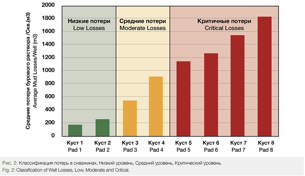
Given these additional complexities, with increased frequency and severity, and also a clear association with certain areas and pads; preventing mud-losses became a more urgent priority. The Team placed an emphasis on ensuring that mud losses were tracked, recorded and categorised with as much detail as possible, including the solutions being applied. This approach then allowed for an emerging suite of categories to be applied (on a well pad basis), see Fig 2., Low, Moderate and Critical. This range allowed for the Team to focus on the locations with the major losses, while progressing with the Development drilling program. This (LEVEL 2) approach, focussed efforts and allowed a new dimension to be added with more exotic materials and approaches. These approaches included considering the use of a potential stress-cage approaches (Alberty and McLean, 2001), as a solution. Such an approach was selected as the nature of the features suggested a re-opening of natural fractures; while not in itself successful as an approach, the data that was gathered suggested an encouraging relationship between the particle-size range which was recorded for future consideration.
During this time period a range of additional and more exotic FLA materials were brought forward for trial; but they were not measurably successful in preventing fluid losses. Given the clear emerging relationship with the ECD, an effort began to look at reducing the ECD through a low-energy drilling approach. This would consist of minimising the pressure losses at each and every stage of the drilling process. Such efforts would include, reducing the pump rate, increasing bit size and examining pressure losses at every location within the system. Indeed, this low-energy drilling approach brought some much-needed relief for a few months as the program progressed. However, at the same time, the production plant was fully commissioned (at 100,000 bopd), but the gas-compression system had not and so the reservoir offtake was at a peak but the reinjection system was not yet optimised. This meant that the reservoir pressure was continuing to fall, particularly under the gas-cap where no injection was taking place, and with the reservoir pressure falling so to was the associated fracture gradient. Therefore, while helpful, a low-energy drilling approach would only potentially provide a very short-lived respite as the situation continuously deteriorated.
Reduced Hydrostatic Head (Level 3)
The next level of consideration was using a reduced hydrostatic-head (LEVEL 3), but with a single phase, this single-phase is a key aspect as more involved energised fluids (as we shall see), bring an entirely new level of complexity. The existing drilling fluid was a Water Based Mud (WBM), a drilling system which had been optimised over several years. However, consideration was now being given to using alternative mud systems. In fact, while the low-energy drilling approach had been underway, a project had been in implementation to drill a well with an Oil-Based Mud (OBM), using a diesel-formulated base fluid that would potentially reduce the ECD to within an acceptable operating range. In fact, an invert emulsion OBM system was trialled (at great expense), and the unfortunate reality of this system was that an increased associated frictional loss meant that the ECD was not that much more of an improvement over the WBM system. In fact, this low achievement in the ECD reduction is not unusual moving from WBM to OBM; on occasion it can be sufficient but in this case it was not. Considering the additional costs of the OBM preparation; meant that such an approach would in fact be uneconomic as an ECD solution. Such costs and complexities are exacerbated even more so when one considers the long-term liability, management and disposal of drilling waste that is directly associated with OBM mud and drill cuttings.
Hollow Glass Spheres (Level 3)
At this stage, it very much looked as though the initial popular but complicated and expensive consideration of using an energised fluid would be the only option left; however considerate engineering was not yet finished. While it looked as though directly replacing the liquid phase of the drilling mud would not in itself be a successful approach, there was always the option of replacing part of the mud phase (See Fig. 1). This option, to replace part of the mud phase, is not as well reported nor indeed applied; but is potentially just as equally capable of achieving the desired result. This approach if applied utilises a well developed oilfield product that is more commonly referred to as Hollow Glass Spheres (HGS), (see Fig 3.).
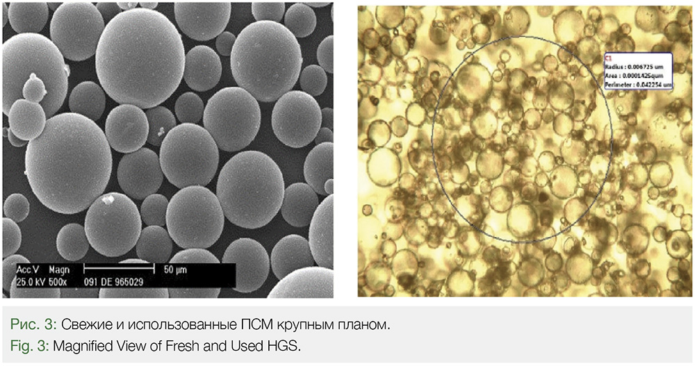
HGS has been around for a while (Block et al., 1991), and are often used as an additive with cementing operations to reduce the ECD in order to avoid fracturing during cementing operations (Arco et al., 2000). In the same way as with cement, they can be used as a simple additive in the drilling mud, displacing other solids agents (and liquid phases), as they are lighter than hydrostatic (they float in water) by design. The result is an overall reduction in the drilling mud SG, which as a result can be as low as 0.70 SG, depending upon the HGS type and the solids-fraction that is utilised.
To consider this as a potential option, a feasibility study was performed and a manufacturer of HGS identified and contracted as a reliable source for the HGS material selected. This feasibility study has largely been reported in the recent paper (Rylance et al., 2021) at the OTC, and will also be updated further at the planned SPE RPTC in October (Sherishorin et al., 2021). A conservative approach was taken to the HGS material selection for the Pilot program to be sure that there would be no adverse issues, with a crush strength of 10,000 psi being selected. Post the successful pilot this is now under review with a 7,500 psi material being the new choice. This reduction in crush strength will dramatically reduce the costs of the material as well as significantly reduce the SG while reducing the % vol fraction of the solids added. As at the lower crush strength, HGS typically has a lower SG.
For the HGS Pilot drilling program, sufficient HGS material was mobilised for a three well trial, including both multi-lateral and horizontal wells. At the same time sufficient hand carried HGS sample material was made available for both laboratory and mechanical testing; and representative examples of our WBM mud were prepared and made available for testing as well. The testing went well, and it was determined that HGS could be added to our conventional WBM, displacing the liquid phase and resulting in a significant reduction in the SG. In fact, the addition of the HGS was able to reduce the SG of the WBM such that a static 0.88 SG could be achieved which would deliver an ECD of 1.01 SG which would be well below the threshold losses initiation value of 1.17 SG.
Hollow Glass Sphere Pilot Programme
The three well pilot, Well A, Well B and Well C, was a complete technical success. In the case of all three wells, when drilling with HGS no mud-losses occurred on these Pads where losses had been experienced and wells curtailed early in all previous drilling attempts. Operationally things went well, though the standard centrifuge(s) failed to efficiently separate the cuttings and HGS material in the used mud.
This minor setback will be addressed during the full-field deployment when the mud management will be centralised, and a specialised centrifuge will enable better mud processing (thereby recovering the HGS for eventual reissue and reuse). This centralised mud approach is much more efficient as well, because as we can see from Fig 2. that only some Pads require this technically advanced approach.
On one of the Pilot wells, due to the poor centrifugal equipment performance, the Team allowed the well to drill on while loading the mud with drill cuttings. On this well the ECD was allowed to increase from below the original threshold to a level as high as 1.32 SG without the onset of mud-losses. When the well was swapped to a lower SG, HGS free mud, mud-losses began immediately; returning to a HGS fluid the mud-losses immediately stopped again. This is clear evidence of the stress-cage effect that we had tried to achieve within the LEVEL 2 engineering assessment; something which will now be built into the forward programme.
Forward Planning and Scale-Up
With a successful Pilot having been performed, the next stage of the engineering planning is now being put into effect, with full-scale deployment taking place at the earliest opportunity. The cost effectiveness of the use of HGS, versus the extensive and increasing mud-losses, NPT and under-drilling effect were self-evident and demonstrable in terms of the Net Present Value (NPV). As the next phase will be focused, materially optimised and material reused, the cost/value relationship is expected to continue to dramatically improve from its already currently favourable position.
Complex Alternatives
If at the beginning of this journey the Engineering Team had followed the more popular route and been thinking ‘zebras’ instead of ‘horses’, then they would have embarked on an immediate LEVEL 4 solution of energised fluids. While there are niche applications for such a solutions there are many, many disadvantages to the use of energised fluids.
These disadvantages have been very well documented over the years but can be summarised in a few simple statements: COST, the cost of using energised fluids is staggering, as well as the proposed gas-phase generation and additives materials themselves there is the additional equipment. With the pressure at surface in the system, a rotating-head is required as well as a swathe of additional handling equipment. Surface returns need to be managed with specialised separators, and all of this must be rigged up and rigged down each time a reservoir section is entered. The alternative, supplying such a spread to each and every drilling rig would be completely unrealistic in terms of cost and scale. In addition to these aspects, the introduction of a 2-phase fluid means that communication with the drilling BHA has potentially been lost. In a development where multi-laterals are being drilled in extremely thin reservoirs, there is no more important BHA capability than this; so likely even more funds are required to provide a new form of communication, such as electromagnetic, use of repeater stations and other more costly, complex, and technically difficult approaches.
Even after all this, if anyone still believes that energised fluids are the correct approach; then there are the safety aspects to consider. Using energised fluids, means that there will be excess pressure at surface at all times; during the drilling operations in the reservoir. The HSE risks will rise exponentially and over a multi-rig and multi-well program the potential for a loss of primary well control incident taking place is dramatically increased. It is in fact no exaggeration to say that an incident is almost guaranteed to occur over a major campaign period.
Can energised fluids be utilised to perform Measured Pressure Drilling (MPD) efficiently, of course they can, but that does not mean that they must be used. Don’t let engineering bias, due to your own technical interest drive your solution, let the requirement drive the solution. “When you hear hoofbeats, think horses not zebras” and you won’t go far wrong.
References
Alberty, M. W. and McLean, M. R. (2001, January). Fracture Gradients in Depleted Reservoirs – Drilling Wells in Late Reservoir Life. Society of Petroleum Engineers. https://doi:10.2118/67740-MS
Aliyev, S.M., Rylance, M., Chernokalov, I.A., Zaev, K. A., Gorbov A.N. and Makarov, A.P., TYNGD, (2017, Oct). Drilling Progression in the Srednebotuobinskoye Field Development. SPE RPTC, Moscow, Russia. SPE-187712-MS.
Arco, M. J., Blanco, J. G., Marquez, R. L., Garavito, S. M., Tovar, J. G., Farias, A. F., & Capo, J. A. (2000, January ). Field Application of Glass Bubbles as a Density-Reducing Agent. https://doi,org/10.2118/62899-MS
Block, J., Latt, J., Rice, R. W. et al. (1991) Method for making Low Sodium Hollow Glass Microspheres. U.S. Patent No. 5069702.
Rylance, M., Aliyev, S.M., Zaev, K.A., Chernokalov, I.A., Gorbov, A.N., Makarov, A.P., Grinchenko, V.A.., Sultanov, R.B. and Yanyshev, A.G. (2017, Oct) A Multi-Disciplinary Multi-Stage Approach to Delivering Multi-Laterals in the Srednebotuoninskoye Field. SPE RPTC, Moscow, Russia. SPE-191514-ms.
Rylance, M., Tuzov, Y., Aliyev, S., Gorbov, A., Galitskiy, I., Makhmutov, D., Grinchenko, V.A., Sultanov, R.B., and Levanov, I. (2018, Oct) Fishbones, Wishbones and Birch-Leaves, Multil-ateral Well Design on the Srednebotuobinskoye Field in Eastern Siberia. SPE RPTC, Moscow, Russia, SPE-201989-MS.
Rylance, M., Tuziva, Y. and Sherishorin, V. (2021, August) Drilling With Glass And Air: Using Hollow Glass Spheres To Address A Wide Ranging Drilling Challenge In A Safe, Efficient And Cost-effective Manner. OTC, Houston, Texas. OTC-31070-MS.
Sherishorin, V., Rylance M., Tuzov, Y., Krokhaleva, O., Tikhonov, E., Chirkov, O. and Ivanov, R. (2021, Oct). Hollow Glass Spheres (HGS) in Drilling Fluid: Case Study of Preventing and Mitigating Total Losses. SPE RPTC, Moscow, Russia. SPE-206447-MS.
Author:
Martin Rylance, THREE60 Energy Group