Identifying and Recording Drill Pipe Operating Time Using RFID Tags
This article describes a prototype of an information system that allows you to track the movement of drill pipes, record their current physical wear, as well as the accumulation of fatigue damage using RFID technology.
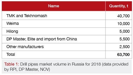
Drill pipes are one of the most capital-intensive cost items for any drilling enterprise. Costs for acquiring new drill pipes is averagely about 20-25% of the capital investment fund. Considering the useful life of drill pipes, which varies from 2 to 6 years, depends on the manufacturing quality, operating conditions and timely repair. The result is an impressive amount that companies have to invest in order to maintain their stock of drill pipes in good working order. For example, in 2018, Russian drilling operators purchased 63,700 tons of steel drill pipes and decommissioned about the same for scrap (Table 1).
In spite of the fact that great importance is attached to the careful treatment of drill pipes at enterprises, the situation is generally far from ideal in real life. According to the established practice, the recording of drill pipes is conducted non-individually for each pipe, but by sets (the actual recording at production site is meant here, each of the drill pipes is a separate fixed asset according to the accounting). When new pipes arrive at the enterprise, technical specialists form a new set, draw up a passport for a set of pipes, and then the pipes are moved to the drilling rig for commissioning. The history of pipe operations, including the operating time per drilled meters, circulation hours or rotor revolutions, is recorded by technical specialists for the set as a whole. As a result, the real condition and current life of a separate drill pipe cannot be reliably determined, except by the external signs of its physical wear during the inspection.
It often results in a situation when a practically new set can be decommissioned due to several cases of drill pipe washouts (Fig. 1). As a rule, washout becomes the result of a critical accumulation of fatigue damage in the body of a drill pipe. But since the flaw detection equipment can determine pipes with a critical accumulation of fatigue damage only at a stage when fatigue microcracks have already been formed and the pipe’s life is nearly ended, technical specialists prefer to be safe, take the set out of service and move it to the storage base for further write-off.

However, knowing the individual operating time for a pipe, it is possible to pre-reject the fatigued pipes from the set with a high degree of accuracy and keep it in good working order.
RFID Technology
RFID (Radio Frequency Identification) is a contactless data exchange technology based on the use of radio frequency electromagnetic radiation. RFID is used to automatically identify and record assets.

A typical RFID system consists of 3 basic components (Fig. 2):
1. RFID tags
2. RFID readers
3. Software
General Classification of RFID Tags

Structurally, RFID tags are an electronic chip with a metallized antenna. There are several ways to classify RFID tags (Fig. 3) by:
1. Operating frequency.
2. Power supply.
3. Memory type.
4. Design.
By Power Supply:
1. Active tags — have a built-in battery and do not depend on reader energy, due to which they are read at a greater distance, and they can also have various built-in temperature, acceleration, humidity sensors, etc.
2. Passive tags — do not have a built-in battery and receive energy by inducing an electromagnetic signal from the reader. Unlike active tags, passive tags do not emit a radio signal.
3. Semi-passive tags — operate based on the principle of a passive tag, but have a battery.
By Operating Frequency:
1. LF (Low Frequency) 125-135 kHz. “Ordinary” tag cards, key fobs for intercoms and access control systems, capsule tags for chipping of animals.
2. HF (High Frequency) 13.56 MHz. Transport travel cards, wireless bank cards, NFC devices and tags.
3. UHF (Ultra High Frequency) 860-960 MHz. Active tags and real-time positioning systems, alarm key fobs, wireless keyboards, mice.
By Memory Type:
1. RO (Read Only) tags — the data is recorded only once, immediately during manufacture. Such tags are suitable only for identification. No new information can be written in them, and it is almost impossible to fake them.
2. WORM (Write Once Read Many) tags — in addition to the unique identifier, such tags contain a block of write-once memory, which can later be read repeatedly.
3. RW (Read and Write) tags — such tags contain an identifier and a block of memory for information reading/writing. The data in them can be overwritten repeatedly.
RFID Tags for Drill Pipes
The tags made on the EPC Gen 2 (fully Electronic Product Code Class 1 Generation 2) standard are the most common used in the world to identify drill pipes. The EPC Gen 2 standard is developed by the GS1 EPC Global international organization, it also complies with the ISO/IEC 18000-6C standard.

Averaged technical parameters of existing RFID tags for drill pipes (Fig. 4):
1. Standard: EPC Class 1 Gen 2 / ISO 18000-6C.
2. Operating frequency: UHF 863-868 MHz.
3. Memory:
a. EPC — 96 bits, unique tag identifier.
b. TID — 64 bits, tag chip manufacturer and model identifier.
c. User Memory — 512 bits, storing any information.
4. Memory type: RW — read and write of data.
5. Read and write cycles: 100,000.
6. Data storage: 10 years.
7. Degree of protection: IP68 — dust-resistant object that can withstand prolonged immersion in water under pressure.
8. Material: Polyetheretherketone (organic thermoplastic polymer) or stainless steel.
9. Operating temperature, at which the tag is read consistently: −40 °C to +85 °C.
10. Maximum temperature, at which the operability is maintained: −50 °C to +200 °C.
11. Dimensions: thickness 4–10 mm, diameter 10–28 mm, weight 8–30 g.
12. Reading radius: 0.5–1.5 m.
13. Cost: $10–$25.
Installing RFID Tags into Drill Pipes
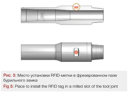
The most convenient place recommended by manufacturers to install RFID tags is an area of the milled slot on the body of tool joint on the pin side (Fig. 5).
Installing the tag not in a slotted area, but on a rounded surface of the tool joint is also allowed, but in this case the tag shall be further deepened into the body in order to protect it from possible damage due to abrasion of the surface of the tool joint. As the tag deepens, its ability to read by a scanner deteriorates, and the reading distance also decreases, as the surrounding metal shields the RF signal between the tag and the RFID reader.
To install the RFID tag into the body of the tool joint, a seat is drilled (Fig. 6). Any drilling machine that capable to reliably fix the drill pipe (including in field) can be used for drilling. During drilling it is essential to ensure the specified diameter and depth of a seat to correctly install the RFID tag.

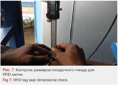
Depending on its design, the RFID tag can be installed by pressing in or screwing in. The thread is tapped with a required pitch when installation is made by screwing in the seat. Before installing a tag, the seat dimensions are checked with a special template (Fig. 7), and a small amount of heat-resistant sealant is applied to the bottom of the RFID tag.
The RFID tag can be additionally attached with glue after installation. The RFID tag cannot be removed after installation; so if a replacement is necessary, it shall be drilled and a new tag shall be installed into the previous seat.
Checking the Drill Pipe for Tension, Torsion and Fatigue Strength
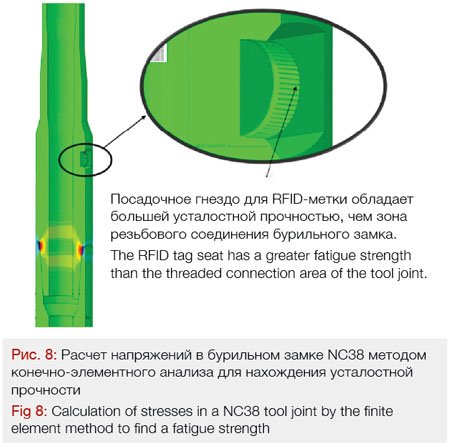
Before drilling the seat, it is important to ensure that this operation does not weaken the structural integrity of the tool joint, does not reduce its strength characteristics, and fatigue strength. For this you need to perform checking calculations, in which the tool joint strength in the area of RFID tag seat is compared to the most vulnerable places: contact area of pin and box threaded connection.
An example of such a calculation for the NC38 single-shoulder tool joints (for 89 mm drill pipes) and NC50 (for 127 mm steel drill pipes) having the S-135 strength group is given below.
The results of comparison of tool joint areas according to the fatigue strength are given in Table. 2. It has been determined that a threaded connection of the pin has a lower fatigue strength than the area of the RFID tag seat (Fig. 8).
The analysis results for tensile and torsional loads are given in Table 3. It is determined that the pin and box threaded connections are weaker than the area of the RFID tag seat.
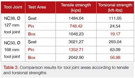
Thus, it may be concluded that after the RFID tag seat is drilled, the joint tool pin remains the weakest place in calculating tensile and torsional loads, as well as fatigue strength. Considering the fact that a body of the drill pipe is even weaker than the pin, it may be concluded that the RFID tag seat does not violate a structural integrity of the drill pipe and does not impair its strength characteristics (Fig. 9 ).

In case the new drill pipes are acquired, such checking calculations, as well as the installation of RFID tags shall be entrusted to the manufacturer. Thus, the drilling enterprise does not bear additional risks and has the ability to obtain the drill pipes with all additional options (RFID tags, hardbending, internal coating, etc.) on a turnkey basis from a single supplier with maintaining of product factory warranty.
RFID Readers
2 types of RFID readers are used to scan the RFID tags installed in drill pipes:
1. Mobile RFID readers.
2. Stationary RFID readers.
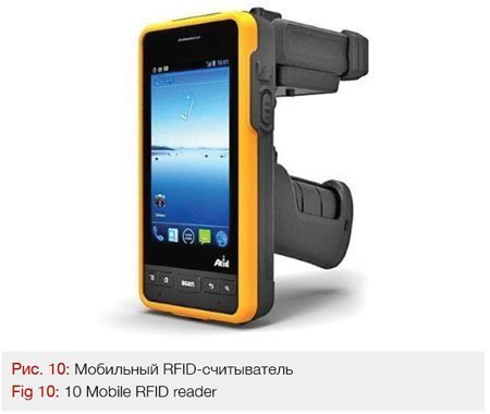
The mobile RFID readers are used to speed up and reduce the labour intensity of drill pipe inventory, search, stock control, and movement operations (Fig. 10). The mobile RFID readers compliant with the EPC Class 1 Gen 2 standards can record tags at a distance of up to several meters. There is a large range of such devices, including those made in the form of rugged tablet PCs with a good protection class, allowing them to be used in the field.
The stationary RFID readers can be designed as a ring and are installed on a rotary platform or under a drilling rig rotor (Fig. 11). Antennas that connected to a common reader and surround the tag recording area inside the ring on all sides, are mounted inside such a ring around the perimeter. When a drill pipe with RFID tag passes through a ring, it is automatically read.

Today, many companies involved in the implementation of RFID technologies are developing similar stationary RFID readers, but only a few manufacturers can offer samples ready for industrial use, which still limits the implementation of such equipment at drilling enterprises.
The mobile and stationary RFID readers shall be connected via the Internet link to the informational system database, where all information on drill pipes is accumulated. As drill pipe operations are processed and RFID tags are read, this data is transferred to the database, where information on their condition and location is updated.
Drill Pipe Recoding Information System
A separate information system shall be deployed to process the data received from RFID readers. The information system consists of 3 basic components:
1. Database with user interface to store and process information.
2. Android application for a mobile RFID reader.
3. Software for a stationary RFID reader.
The database stores the following information on drill pipes (example):
1. General information: pipe type, manufacturer, serial and inventory number.
2. Technical parameters: strength group, thread type, upset type, internal coating, hardbanding.
3. Geometric parameters: diameter, wall thickness, length.
4. Current wear: wear class, bending, thread condition, measurement results.
5. Pipe repair and inspection history: date, work performed, contracting organization.
6. Operating time: drilled meters, circulation hours, rotor revolutions, fatigue damage.
7. Operation history: drilling rig, well, operation period.
8. Current location.
The separate software should be developed or purchased to synchronize data received from RFID readers with a database. It will allow you to receive a signal from the scanned RFID tag, process it and transmit it to the information system database for further analysis. As an example for mobile RFID readers, this could be a corporate Android application that can be installed on any Android device (smartphone, tablet PC). A technician working with such a mobile RFID reader in the field will be able to draw up a certificate for incoming inspection, flaw detection, inventory of drill pipes, as well as analyze the history of pipe operation in the Android application.
The stationary RFID reader should be equipped with a minimum amount of software sufficient to connect to the Automated Control System (ACS) of the drilling rig. The data from the stationary RFID reader will be delivered in the same way as from a conventional sensor, after which it will be transmitted with the general flow of information to the office of the drilling enterprise and then to the drill pipe recording database. The stationary RFID reader can be optionally connected to a mud logging station at the drill site, where the data on read RFID tags will be transmitted along with the data flow from the mud logging sensors.
Scenario for Performing the Drill Pipe Inspection using RFID Tags
A typical process of drill pipe inspection at a pipe yard or field may be as follows:
1. The inspector sequentially scans RFID tags on each drill pipe using a mobile RFID reader in the process of pipe inspection.
2. The inspector records data on the current wear and diagnostics results of drill pipe into the equipment card of the RFID reader.
3. Upon completion of the work, the inspector saves a document with pipe inspection results on the mobile RFID reader and sends it via the Internet link to the information system database.
4. The database operator receives a document with pipe inspection results, checks it and passes it through the information system.
5. When each of the drill pipes indicated by a unique identifier in the pipe inspection results is passed through, the data on current wear, required repair, and actual location are updated.
6. The actual availability of drill pipes in a drilling rig set is automatically checked with the database information at the same time, i.e. unscheduled inventory check is performed.

The results on performed pipe inspection are made available to all users of the information system for further work (Fig. 12).
Scenario for Recording the Drill Pipe Operating Time using RFID tags
The RFID technology also allows you to build the process of operating time recording in real time:
1. The drill pipes equipped with RFID tags and recorded in the information system, are delivered to the drilling rig. The rotary platform of the drilling rig is equipped with a stationary RFID reader.
2. When the pipe is run into the hole, it passes through the ring where a RFID tag is read. Information on the read tags along with other sensor readings is transmitted to the mud logging station.
3. The mud logging station transmits data on the scanned RFID tags and data on the drilling practices into the information system database via a satellite link in real time.
4. The information system builds a virtual hookup of drill pipes and monitors its operation modes in the well according to logging data. For each of the drill pipe in a hookup, its current location in the well bore is compared with the actual drilling practice.
If a part of lowered pipes does not have RFID tags (for example, the contractor’s equipment), the information system based on the movement of traveling block and the change in weight on hook will independently assign this equipment as unrecognized.
5. At the same time, inclinometry data used to build the actual well trajectory is fed into the database through manual entry or through integration with third-party software.
6. Considering all the collected data, the information system calculates the well trajectory, tensile and bending stresses acting on the drill pipes. Calculates the number of drilled meters, rotor revolutions, circulation hours, as well as the accumulated fatigue damage for each of the pipes in a hookup (Fig. 13). If the drill pipe reaches an operating time limit, the information
system will deliver a warning on the inadmissibility of its further operation to technicians.

Thus, there is a constant update of data on the current operating time of drill pipes and their remaining life, which is available to all users of the system in real time.
Conclusion
The implementation of individual recording of drill pipes using RFID tags according to the scheme described in this article will enable drilling enterprises to increase the efficiency of their operation and reduce the cost of the life cycle:
1. To increase the useful life of drill pipes by at least 20% due to reliable information on the current condition and remaining life, which allows to operate the pipes to the maximum permissible wear, rather than to write them off ahead of time based on general data on the set.
2. To reduce the number of pipes in a set to the one directly required for drilling a well. While shaping up the set of pipes their number is to be calculated with reserve of at least 5% with account of probable sorting out in the process of operation, since pipes of different sets are now allowed to be mixed to each other or to other new pipes (as their run life data would be incorrect then). With the introduction of the individual accounting of pipes with the use of RFID, the drilling layout can be assembled from any existing pipes.
3. To reduce the cost of flaw detection and minor repairs of drillpipes by -25%. Introduction of RFID-identification will make it possible to repair only those pipes that really require some repair, based on the data of their individual run life. In stead of replacement of a complete set of pipes in the process of drilling, to repair them, it will be sufficient just to replace the most worn out portion of them, thus changing over from the strategy of the «Classic Planned and Forced repair» to the strategy of «Condition-based repair».
4. To reduce the risk of accidents related to destruction of drill pipes due to washout or failure by -30%. The information system will provide with recommendations on sorting out of drillpipes or alteration of their position in the hookup before RIH operation, based on their current run life.
5. To reduce the fleet of drill pipes by -5% by excluding from the company’s fleet those pipes that have lost or unverified background of their operation and run life. The background of each pipe is stored in the information system and cannot be compromised.
6. To compare the real lifetime of drill pipes produced by different manufacturers within the correlated conditions of operation. The individual run life of pipes will demonstrate differences in the delivered products to select the best possible suppliers in the price/quality ratio and will enable the increase of usable life expectancy by +10% more, as minimum.
In the aggregate, the above advantages will provide a significant economic effect for any drilling enterprise, which is a multiple of the costs for RFID implementation.
References
Deployment of Radio Frequency Identification (RFID) in the oil and gas industry – Norwegian Oil and Gas Association Guideline No. 112, 2010
RFID for Oil and Gas Industry: Applications and Challenges – Emad Felemban, Adil A. Sheikh, 2013
EPC™ Radio-Frequency Identity Protocols Generation-2 UHF RFID – GS1 EPCglobal Inс, 2015
Fatigue Failure of Drill Pipes, Its Forecasting and Prevention — ROGTEC Magazine No. 52, Oleg Fomin, 2018
Oleg Fomin, Consultant, Oil & Gas Production Industry