Identifying the Real Structure of an Oil and Gas Reservoir and its Effect on Recoverable Hydrocarbon Reserves Part 1
Yuri A. Limberger, Independent Expert
Summary
An oil and gas reservoir structure is currently presented in a highly simplified form. It is assumed that all the intercommunicating (open) pores are filled with hydrocarbons and a residual water film. This concept of a reservoir model is used to process and interpret logging data, build petrophysical relationships, perform hydrodynamic calculations and estimate oil and gas reserves by the volumetric method. The simplification of a reservoir model clearly contradicts the results of the core analysis performed to determine the structure of the rock pore space and is a source of fundamental errors in evaluating some reservoir parameters. This results in excessive over-estimation of in-place and recoverable hydrocarbon reserves. Based on the results of studies to determine pore size, their distribution in the rock and their contribution to fluid flow (filtration), performed on numerous samples from different fields, a new, more adequate reservoir structure model can be substantiated. This model enables estimation of the recoverable hydrocarbon reserves by the volumetric method with an accuracy level which could not be achieved using the current assumed model.
Introduction
Modern methods of processing and interpretation of the results of sub-surface exploration are based on certain concepts about the structure of rocks and beds penetrated by a well, as well as on the hypothesis of hydrocarbon pool formation. Initially, there were mineral deposits of various types and sizes. Spaces between solid particles, i.e. voids, also varied and were filled with water. Thus, difference in pore size was bound to occur at the time of deposition.
In the course of diagenesis, as the deposits subsided they began to be affected by the overburden stress. The deposits were compacted and transformed into rock. Compaction is a phenomenon typical of all sedimentary rocks making up rock sections in oil and gas fields.
A Complex (Dual System) Reservoir
The compaction process in a potential reservoir (e.g. sandstone) and a potential cap (e.g. shales) occurs simultaneously but differently: in reservoirs it happens as the result of the changing position of mineral matrix particles in relation to each other, and in shales, as the result of decreased distance between structural layers. In any case, reduction of voids is observed due to increased volume of minerals in a rock unit. The decrease in volume of voids is accompanied by reduction in size of original pores and outflux of free water. The outflux will continue until relevant interaction forces between water and matrix come into effect. The water then cannot be removed and stays in the pores; in this case removal of the water is additionally prevented by low compressibility of the water itself. The water remaining in the pores – residual water – is the main reason why it is impossible for fluids to flow through such pores resulting in impermeability.
Pores of different sizes in rocks contribute to open porosity in reservoirs and caps. Rocks or part of them will only be permeable if they contain an interconnected void network which can make fluid flow possible. Thus, the main condition for such a network to exist should be: Φ > 0.
A rock will be impermeable and unable to have a fluid flow in the following cases:
а) when it does not contain any voids, i.e. Φ=0;
b) when it does contain voids, i.e. Φ >0 but they are not interconnected;
c) when it does contain voids which even form an interconnected network, i. e. Φ > 0, but void size is so insignificant that fluid flow is not possible.
If the above arguments are correct then open porosity of a reservoir before a hydrocarbon pool is formed would consist of two interconnected parts. One of them is permeable and filled with free water which has not been removed, and the other one – impermeable and filled with residual water. This assumption could be verified by analysing rock samples to study pore distribution by size and its contribution to permeability. Various methods of such analysis are described in publications.
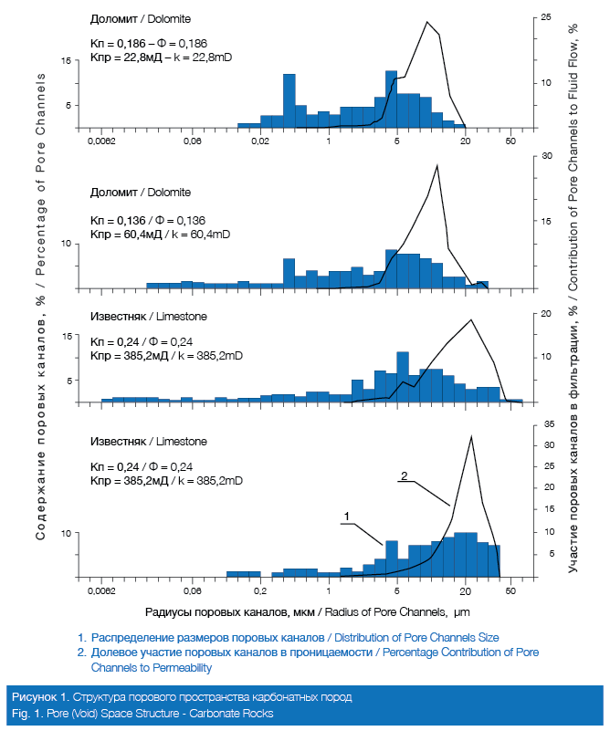
Figs. 1 and 2 show examples of pore distribution by size obtained by the mercury penetration method. The “x” axis shows size of pore channels. Using data in the left part of the “y” axis one can evaluate contribution of pore channels of selected size to the sample porosity; this contribution is determined as a percentage of the indicated sample porosity. Using the data on the right part of the “y” axis one can evaluate contribution of pore channels of selected size to the sample permeability; this contribution is determined as a percentage of the indicated sample permeability.

The Figures show examples of pore distribution by size and its contribution to the permeability of carbonate (dolomites, limestones) and clastic (sandstones, shales) rock samples. They demonstrate that in all the reservoir rock samples rock permeability and the ability to have a fluid flow is provided not by all the pore channels but only by a part of them (part of voids), even in the cases when the samples show high porosity and permeability.
The Real Structure of an Oil and Gas Reservoir
Gradual formation of a hydrocarbon pool will begin in such a reservoir. The hypothesis of accumulation suggests that hydrocarbons migrate from the places of origin in a dissipated form through rock mass and accumulate in pools. Once inside the pool they rise through the water, displacing free water from the pores and substituting this water. The final result is the current model: all pore space is occupied by hydrocarbons with a residual water film.
This naturally gives a rise to a question: how could hydrocarbons have filled all the reservoir voids if part of the reservoir with open porosity is not permeable? Hydrocarbons which reached the reservoir would move through it via the paths of least resistance. Such paths could only be the pores which provide permeability. Thus, it would be impossible for hydrocarbons to fill in all open pores by removing not only free but residual water from them. They would fill only those open pores which could enable fluid flow, i.e. only the part which is permeable.
The author has analysed over 1600 results from studying pore space in rocks. Not a single reservoir sample from the oil, gas and water-bearing parts of the pool (which form the majority of the studied samples) showed contribution by all pores, i.e. the whole void volume, to permeability and fluid flow. In all the samples, a certain part of the rock void volume does not contribute to fluid flow, remaining fluid-impermeable. In non-reservoir samples (over 300 samples) typical rock permeability to air (k << 1 mD) is provided by a tiny proportion of void volume. The stated facts prove the similar nature and cause of the phenomenon both in reservoir and non-reservoir rocks: a certain part of void volume does not contribute to permeability due to this part being filled with residual water. The difference is that for non-reservoirs this is typical of all the void volume; while for reservoirs – only for the part with open porosity.
Thus, a reservoir has two interconnected pore networks which exist at the same time. One of these systems enables permeability and fluid flow in the reservoir while the other prevents it. The first system – effective porosity – serves as a container for mobile fluids (hydrocarbons and water) in the respective parts of the pool, while the other –non-effective porosity – acts as a container for residual water in any part of the pool. In other words, an oil and gas reservoir structure is not as the currently assumed one, but is considerably more complicated. Part of the reservoir with interconnected is filled with oil or gas and a residual water film. This part is permeable and enables fluid flow. The other part of the reservoir with interconnected is filled with residual water, is impermeable and does not enable fluids to flow.
Substantiation of a reservoir structure is a scientific challenge. Solving it would provide new opportunities for practical application. Some of the specific areas of practical use of the new reservoir model are considered below.
Direct Determination of Oil Saturation
Oil saturation is one of the parameters which affect the volume of deposits in a pool. Determination of this parameter is a necessary and compulsory procedure when estimating oil deposits by the volumetric method. In practice this procedure is performed by taking some measurements in a well and using empirical Archie functions based on the results of core analysis. The Archie equations are the following:
F = Ro/ Rw = a/Φm (1) and I = Rt/ Ro = 1/Swn (2), where
F – formation factor
I – resistivity index
Φ – porosity
Ro – resistivity of a rock fully saturated with water
Rt – resistivity of a rock filled with water and oil
Rw – resistivity of a water
Sw – water saturated
So – oil saturated
a.m.n – empirical constants.
An interpreter would use the following process: formation resistivity and porosity are determined by well measurements. F is determined by using established values of Φ and applying equation (1). Ro =F●Rw is calculated.
I = Rt/Ro is calculated and Sw is determined using equation (2). Oil saturation factor is So = 1- Sw.
Using this approach to estimate Sw, it is assumed that in equation (1) m=const, although m in any reservoir, in any pools, is always m≠const. It is also assumed that the physical and chemical properties of residual water in an oil-bearing part of the pool are identical to the physical and chemical properties of water in the water-bearing part of the pool. Therefore, when calculating Ro for the oil-saturated part of the pool, the value of Rw is assumed to be equal to its value for the water-bearing part. When determining equation (2), the core study method is such that a single value of Sw is always compared with a single value of Rt. Тhus, it is assumed that Rt is a function of Sw alone. Consequently, calculation of Ro for the oil-bearing part of the pool and determination of oil saturation are based on a number of unsubstantiated and unproven assumptions.
Formation resistivity in general depends on the rock matrix conductivity, conductivity of water in pores and the nature of the distribution in formation voids of phases which either conduct electric current (water) or do not (hydrocarbons). It is generally believed that conductivity of matrix minerals is low and can be ignored, as could be the case with the distribution of current conductive and non-conductive phases. It is, therefore, believed that the resistivity of a water-bearing formation depends only on its porosity and the physical and chemical properties of the water in the pores while resistivity of an oil-bearing formation depends only on porosity, water saturation and water properties.
The majority of minerals forming a reservoir matrix do, indeed, have extremely low electrical conductivity. Thus, average conductivity of such minerals as anhydrite, calcite, dolomite, quartz, albite (white feldspar), biotite, amphibolite, etc. is in the range of 10-8 10-17 S/m.
Therefore, ignoring the effect of matrix electrical conductivity on measured formation resistivity is justified. However, one should also bear in mind that the volume of core taken and studied in a laboratory, is incomparably small when considering the volume of rock in a pool. It can’t be guaranteed that matrix electrical conductivity would remain low in all reservoirs in the pool.
However, ignoring the effect of distribution of current-conductive and non-conductive phases on measured formation resistivity is not justified. In practice, this factor is not given sufficient attention, which is wrong. C. A. Grattoni and R.A.Dawe experimentally proved [3], that an oil-bearing formation resistivity and, correspondingly, resistivity index, depend considerably not only on the degree to which voids are filled with water and on the water properties but also on the nature of distribution of conductive and non-conductive phases in pores. Subsequently, (and it has been proven by experiments) an oil-bearing formation can have different resistivities with the same water saturation factor. Vice versa, the same oil-bearing formation resistivity could correspond to different water-saturation factors.
The nature of the distribution of hydrocarbons and residual water film (i.e. conductive and non-conductive phases) in a specific formation is not originally known. Furthermore, it is distorted by mud filtrate ingress.
The factor of spatial distribution of phases would always exist in a formation filled with hydrocarbons and its effect is equivalent to over-estimating the measured formation resistivity. This results in under-estimation of the water-saturation factor determined by equations (2), made by the standard method. Eventually, this would lead to over-estimation of the oil-saturation factor.
The drawback of the current approach to determination of oil-saturation factor is that it is done by an indirect method. This is a significant drawback which could not be eliminated by using any methodological tricks. It is futile to expect that this problem could be solved by increasing the number of rock core samples analysed in a laboratory. One could theoretically suggest studying the distribution of conductive and non-conductive phases on an unlimited number of core samples. But even performing such studies would not dramatically change the situation with determination of a water-saturation factor because in a specific formation studied in a real mining condition, actual distribution of conductive and non-conductive phases will always remain unknown to the researcher. Therefore, it would be unrealistic to expect to find any analogue of phase distribution by studying core samples.
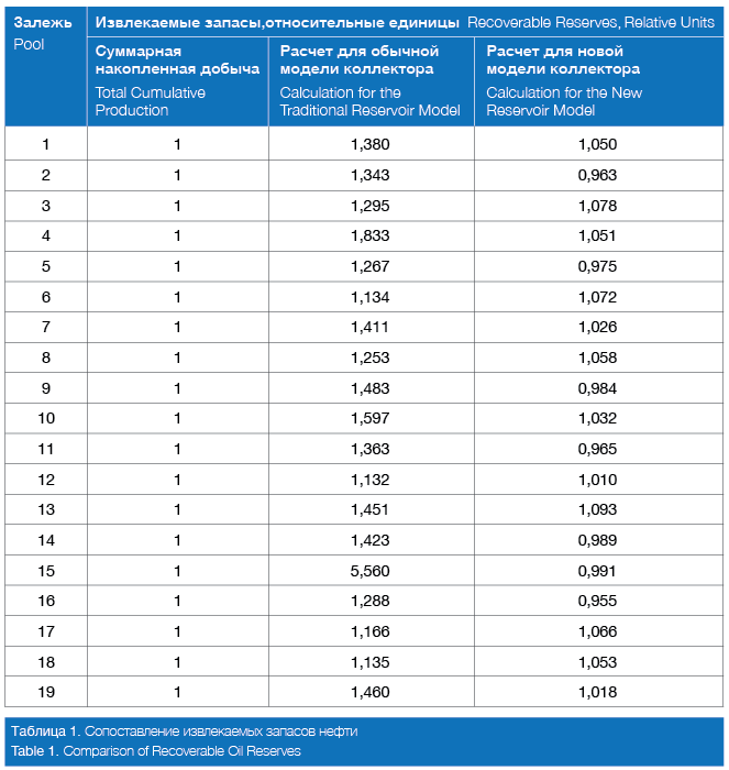
The way to resolve the current situation is by radical review of the actual approach to achieving the set objective. An oil-saturation factor should be determined not by an indirect method but by a direct method. Such a method would be impossible to apply using the currently assumed reservoir model. Direct determination of the oil saturation is used in a new reservoir model and does not require knowledge of the Archie equations, formation resistivity and type of rock wettability. The results of applying the new estimation method for oil saturation are considered below (Table 1).
Oil and Gas Recovery Factors
It is considered that the reserves initially in place (geological reserves) could never be completely recovered and delivered to the surface. Is there any substantiation of this point of view, and if there is, what is the essence of it?
The impossibility of complete recovery of free gas reserves from sub-surface is substantiated by physical factors: when gas pressure in a pool becomes equal to surface pressure + pressure of a gas column from surface to pool, drawdown, which enables recovery of gas from the pool rocks and its movement to the wellhead, disappears. But the pool itself would still have some energy potential remaining, which means that some gas reserves would still remain there. A gas recovery factor is a calculated value which does not vary significantly from 1 and, therefore, recoverable gas reserves do not vary significantly from reserves initially in place (geological reserves). The accuracy of estimation of initial (geological) reserves pre-determines the accuracy of estimation of recoverable reserves.
Unlike the case with gas, the impossibility of complete recovery of geological oil reserves is assumed as an axiom, i. e. a point which does not require to be proved. However, any axiom was at some stage a theorem which had to be proved, after which it would become an axiom. The proof would normally be very quickly forgotten and the axiom then would be accepted as something that stands to reason without the need for any additional confirmation. It would be reasonable to ask a question: who proved, and when, the impossibility of full recovery of geological oil reserves? There is a simple answer to this question: nobody ever asked it.
The hypothesis of pool formation suggests that hydrocarbons, migrating through rock masses in a dissipated state, are accumulated in reservoirs where the voids were initially filled with water. One could build the following scheme: when a pool is formed the water is displaced by hydrocarbons and during production, oil is displaced by water. If one adheres to this hypothesis one should also use the same approach when studying cores, initially oil should be pushed through a core sample fully saturated with water and then the oil should be displaced with water.
However, it is done differently. A sample is saturated with oil under vacuum after which water is pushed through. Saturation of a sample under vacuum enables oil to reach numerous very small pores which it could never reach in naturally occurring conditions of rock and from which oil could never be pushed out by water injection. Using this study method, oil displacement factor (which is a component of oil recovery factor) would always be below 1, and the results of such studies are used as the basis for a “scientific substantiation” of the myth that recovery of all of the oil contained in a pool is not possible.
Introducing into practice an oil recovery factor (ORF) which is normally considerably below 1 results in an unsubstantiated division of reserves-in-place (geological reserves) into those which could be recovered from the pool and delivered to the surface (recoverable reserves) and those which could not be recovered from the rock (residual). Thus, it is assumed in advance that after an oil pool development most of the oil in a pay formation would remain subsurface.
An oil recovery factor is an unsubstantiated factor which could be easily manipulated and steered in the right direction, depending on set objectives, challenges and subjective views on the issue of oil recovery. Thus, comparatively recently an ORF was a product of three factors: oil displacement, conformance and sweep efficiency. All of these factors are below 1 and their subsequent multiplication reduces the oil recovery factor. Should an “oil recovery increase” be required, one of these factors would be promptly forgotten.
Calculation of Recoverable Reserves
Calculation of discovered reserves by the volumetric method is extensively used worldwide. The calculation formula for the oil is:
Q = SHΦSo (3), where
Q – reserves initially in place (geological);
S – oil productive area;
H – average thickness of an oil-producing part of reservoir;
Φ – average interconnected porosity;
S0 – average oil saturation.
At first glance, using formula (3) appears quite logical. Indeed, a product of oil productive area and reservoir thickness determines the volume of rock in the pool. Multiplying rock volume by void volume and subsequently – by an oil saturation factor determines volume of oil in the voids of pool rocks.
However, using an interconnected porosity clearly contradicts the results of rock sample studies to examine distribution of pore channels and their contribution to permeability. As shown above, part of the reservoir with open porosity is filled with residual water and could not act as a container for oil. Substitution in (3) of an open porosity factor will automatically lead to over-estimating the size of the container filled with oil. If one is also to take into account over-estimation of oil saturation determined by the standard method using function (2), the consequence of using formula (3) will be over-estimation of oil reserves initially in place.
Recoverable reserves are calculated by multiplying in-place reserves by an oil recovery factor which currently requires the knowledge of oil-displacement and sweep efficiency. Displacement efficiency is estimated based on the results of a modelling process using core samples (error in the currently used method was described above). Sweep efficiency is estimated using the results of hydrodynamic calculations based on different well patterns. All of the above takes a long time and involves significant costs.
A new reservoir model allows direct calculation of recoverable reserves without using reserves in-place and oil recovery factor.
From the substantiation of the new reservoir structure model it follows that, if calculating hydrocarbon reserves by the volumetric method, the use of effective porosity and oil saturation (in the area of effective porosity) in (3), (instead Φ and So), will immediately provide the volume of recoverable reserves.
Part 2 Click HERE