Introducing Geosteer Well On Paper™ A New Important Step in the Well Delivery Process
How the Planning Phase can Foreshadow Geosteering Failure
The success of any geosteering process is determined at the planning stage. This article will present the most crucial aspects of well planning which directly impact the effectiveness and efficiency of the geosteering process while drilling. These critical matters, often overlooked or omitted during planning, have a significant effect on the process as their negative impact cannot be mitigated or reversed while drilling. Thus, if not taken into account during the planning stage, they will condemn the well to failure before the geosteering process has even commenced. The article proposes an introduction of a new crucial step in the well delivery process, a Geosteer Well On Paper™ (GWOP) exercise during which all the required steering activity’s due diligence should take place.
Geosteering Horizontal Wells
In conventional deviated drilling, the well path is steered according to a predetermined geometrical plan defined by rigid boundaries of the model. The objective of a conventional well is simply to follow the line as closely as possible. Geosteering is a departure from this convention as it involves the use of real time streaming of logging while drilling data (LWD) to help placing a horizontal wellbore in the most optimal position. The main objective of geosteering is the most optimal reservoir exposure by minimizing non-productive intervals.

Contrary to conventional wells, the targets of a geosteered wellbore are continuously evaluated and modified while drilling. Since the exact trajectory of the well cannot be verified at the planning stage, geosteering acts as a contingency for all the uncertainties and possible deviations from the plan which the well might encounter during drilling (Fig. 1).
Planning of Horizontal Wells
The success of any geosteering process commences on the first day of the planning stage. The operational teams need to have an increased level of awareness in relation to the factors that will directly impact the geosteering process. These factors, if undecided or left to chance, may result in failure to meet the geosteering objectives. The most important points which need to be agreed upon prior drilling include:
• Bottom hole assembly and stabilizers strategy
• Applied survey spacing strategy
• Acknowledgment of structural uncertainties of the drilled target
• Targets definition and their distribution along the well path
• Dog leg severity limitations
• Overall build rate values of the planned trajectory
Bottom Hole Assembly
The type of rotary steerable system (RSS) affects the effectiveness of steering and defines how quickly a desired angle of inclination can be achieved. Commonly, there are two steering concepts in the RSS: point-the-bit and push-the-bit. In general, either a point-the-bit or a push-the-bit RSS allows achieving a maximum build rate of approximately 6 to 8 degrees per 100 ft for the 8-1/2-inch hole size BHA tool (Sugiura et al., 2014) and seemingly both are equally applicable for geosteering purposes.
Yet a vital characteristic of each of the system is their sensitivity to the mechanical properties of a formation. In the case of push-the-bit system, the requirement to push off the opposite side of the borehole to cause a change in the trajectory makes in-gauge holes a necessity for such action. Hole washouts and borehole rugosity can negatively impact the directional performance of these systems. Kicking off a sidetrack in an existing well can also be problematic for a push-the-bit system because the pads become unable to contact the borehole wall due to the hole enlargement that occurs at the kickoff point. Therefore, the push-the-bit system should never be chosen for drilling soft, easily washed out formations (Fig. 2).

Consequently, the choice of RSS system should be based on a type of formation to be drilled. Relatively hard formations will require different RSS type to soft ones. For optimized directional control, a point-the-bit system will have a major effect in soft formations, whereas the side force (push-the-bit system) will have a better result in hard formations (Griffiths, 2009). This characteristic should be evaluated thoroughly based on the type of formation that will be drilled as it will significantly impact the geosteering performance and may hinder achieving required trajectory shape.
Stabilizers Strategy
The bottom hole assembly (BHA) together with stabilizers and drilling collars to be used for drilling are designed during the planning stage. They help to guide the bit in the borehole and play a major part in directional drilling as they help determine the well-bore path and drilling angle.
In a deviated or horizontal hole, gravitational and buckling forces bend any unsupported section of the BHA (Mantle, 2013/2014). Properly designed stabilization therefore, is paramount to prevent these phenomena. On the other hand, one can use this force to work for the desired outcome rather than against it.
There are certain default steering directions (tendencies) that can be built into the drill string. This is fine if done purposely; but if a certain tendency is built into the BHA coincidentally it will significantly hinder manoeuvrability when geosteering. A stabilized BHA can be designed to build, hold or drop angle depending on the location of stabilizers which act as contact points between the BHA and the formation (Mantle, 2013/2014).
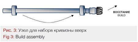
If two stabilizers are widely spaced with one being relatively close to the bit, then the BHA bends between them resulting in the bit deflecting upwards. As a result, the BHA will have a tendency to continuously increase the inclination and simultaneously struggle to perform sharp drops of inclinations. The build assembly (Fig.3) should be used for climbing well profiles where right after landing in the reservoir the trajectory will gradually decrease the TVD values (shallower TVDs) ascending to the well TD.
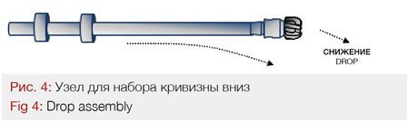
If stabilizers are positioned a significant distance from the bit, the length of BHA between the bottommost stabilizers and the bit bends slightly under gravity, resulting in a tendency for the bit to point down and decrease the well inclination (Mantle, 2013/2014). The drop assembly (Fig. 4) should be used for drooping well profiles where right after landing in the reservoir the trajectory will gradually increase the TVD values (deeper TVDs) descending to the well TD.
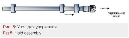
If stabilizers are distributed relatively evenly along the length of the BHA, the bit will neither build or drop (Fig.5). This assembly tends to hold the well inclination and is called a hold assembly (Mantle, 2013/2014). Consequently, it should be used for relatively flat well profiles.
Various other factors also influence the dogleg tendencies of BHA. For example, larger diameter stabilizers and/or drilling collars will constitute a stiffer assembly. Hence the assembly will not bend as easily as if mounted with smaller diameter stabilizers and/or thinner collars. A greater flexibility of smaller BHA size (e.g. for drilling a 6-inch hole) compared to the larger BHA size (e.g. for drilling an 8-1/2-inch hole) allows them to deliver greater doglegs delivery but makes maintaining directional control more challenging.
Survey Spacing Strategy
The inaccuracies that accumulate due to the static survey spacing can create misleading interpretation of the well trajectory position in the subsurface space. The magnitude of the error or the uncertainty depends on how frequently the well is surveyed (Griffiths, 2009). The methods used for calculating the wellbore trajectory include certain assumptions. For instance, the radius of curvature method assumes a smooth wellbore path between the two survey stations; however, the actual trajectory between the two stations may not be such. Therefore, the less frequently the well is surveyed the farther the survey stations and assumptions are made over a longer course of the trajectory, which means a larger error over the entire well path. Consequently, surveying the well more frequently places the stations close to each other and reduces this uncertainty.

Oversight of this phenomenon can lead to critical misjudgement of the geosteering direction, especially in thin horizontally developed reservoir targets, and subsequently result in exiting the reservoir target (Fig.6). The negative effect is enhanced especially for three-dimensional well profiles where the well path requires not only the inclination changes but also the azimuthal direction alterations. The understanding and awareness of all the uncertainty ranges, therefore survey spacing strategy, must be developed for every well path to adequately mitigate these risks.
Structural Uncertainty
On top of the survey uncertainty, which is related to the position of the wellbore in the subsurface space, there is an uncertainty related to the spatial position of the geological model within the three-dimensional subsurface setting, a structural uncertainty.
Structural uncertainty is seldom properly addressed and confronted with the intended trajectory plan. Nevertheless, it has a large and sometimes dominating effect on the reliability of well planning, results of the geosteering (well placement) and ultimately of a reservoir’s production. In the end, without a spatial uncertainty assessment at the planning stage, the risk of erroneous predictions and wrong geosteering decisions is increased (Seiler et al., 2009).
A structural uncertainty phenomenon is a direct result of the seismic uncertainty and its interpretation. Potentially, a very reasonable seismic interpretation can represent several significantly different geological models, any one of which by itself can be confidently and precisely determined in quantitative terms (Soleng et al., 2004).
The seismic uncertainty is a function of various uncertainties, which can have a range of values:
• Uncertainty related to data acquisition and processing (migration)
The range of uncertainty related to seismic acquisition and migration depends on the precision of the measurement and acquisition frequency (data resolution). Seismic data are commonly polluted by acquisition or processing artifacts and noise which may have a strong impact on subsequent seismic interpretation. During the migration process, seismic events recorded on the surface are geometrically re-located in either space or time to the location where the event actually occurred in the subsurface. This process needs to overcome the limitations of geophysical methods imposed by areas of complex geology such as faults, salt bodies and folding which subsequently introduce certain uncertainties into the system. The acquisition and processing are also affected by geological and seismic anisotropies which if ignored may lead to poor seismic imagining, inaccurate well-ties and incorrect interpretation of the data (Bond et al., 2007).
• Uncertainty related to data interpretation
Errors introduced by human interpretation cannot be omitted. Incorrectly interpreted seismic horizons affect the estimated thickness and depth of the reservoirs. In turn high resolution of the seismic data enhances the ability for proper faults and other seismic features identified. Data interpretation uncertainty cannot be resolved by a simple quality control check as it is often not possible for certain horizons/fault planes to be picked up with high accuracy, thus introducing yet another uncertainty on the position of the horizon.
• Uncertainty related to time to depth conversion
Seismic horizons are usually picked on seismic reflectors in time domain. Thus, the biggest uncertainty comes from the time to depth seismic conversion, depending on the accuracy of the velocities used in the conversion. It is common to generate multiple velocity models to understand the likely range of depths for a given horizon (Bond et al., 2007).
• Uncertainty related to well-to-seismic ties
Undoubtedly, one of the most important aspects of working with seismic data is the correlation of well data to seismic data, e.g. the well-to-seismic tie that links geology and seismic response. Some interpreters tie wells to seismic data assuming that the greater amount of uncertainty resides in the seismic data and that the well data are always or almost always correct. Others tend to recognize the limitations of well data and spread uncertainty more evenly between the well and seismic data (Seiler et al., 2009).
The crucial output of the above, is the idea that all the interpretive results should be placed within an established quantitative range of uncertainty. It must be ascertained that the meaning and limits of that range are clearly understood and communicated to all involved in geosteering parties.
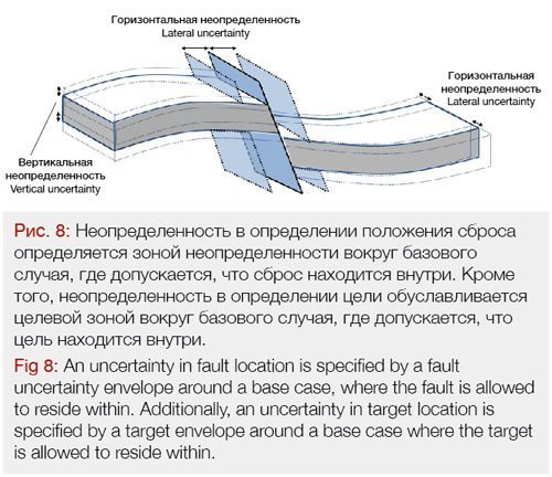
The most common measure of uncertainty is specifying an error bar (uncertainty range) or plus-minus value, e.g. the predicted depth of the formation X is 8500 ft TVDSS ±2% or ±30 ft TVD) for horizons. Fault locations are also inherently uncertain and come with lateral uncertainties related to the position of the fault planes and the plane dips.
Apart from vertical uncertainty especially affecting prognosed formation tops, lateral uncertainty plays a significant role in planning for any horizontally distributed geological features like synforms and antiforms (Soleng et al., 2004) and consequently directly affect the geosteering process.
Another consequence of the spatial uncertainty is the effect on dip/position angle of the planar features e.g. faults (Figs. 7 and 8). Dips of high values (close to 90 degrees) will be especially distorted.

An estimation of uncertainty does not need to be symmetric because the individual factors contributing to seismic uncertainty, especially those that are geologically related, are not necessarily symmetrically distributed (Soleng et al., 2004).
All the factors that control the magnitude of the spatial (vertical and lateral) uncertainties should be examined and their values should be properly estimated. This will impact significantly on the definition of the geological targets and the way a trajectory will penetrate those targets during the geosteering process (Fig.9).
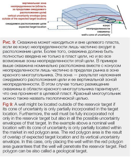
Geosteering the well according to the observed geology assures optimal well placement and adds significant value compared to drilling it geometrically based on surveys with their associated uncertainty following pre-drill planned trajectory.
Targets Definition
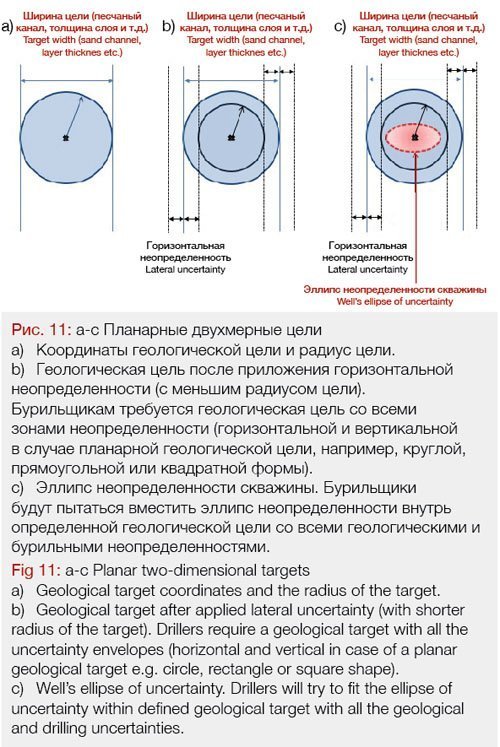
During the planning stage, the geological target, the drilling target and the size and shape of the cone of uncertainty need to be defined, agreed upon and superimposed all together. A geological target is usually specified, based on the expected reservoir dimensions at a given location. The geological target needs to be at least the same size as the drillers’ target, but not smaller, to allow the well to penetrate the geological target with all the uncertainties (including the cone of uncertainty at the given location).
To ensure that the well will actually penetrate the geological target, the drillers’ target must be adjusted (e.g. reduced) so the entire ellipse of uncertainty fits within both the geological and the drillers’ targets (even if a well penetrates the target on the edge of the drillers’ target and on the edge of the ellipse of uncertainty). To visualize this concept, see figure 10, 11 and 12 below.
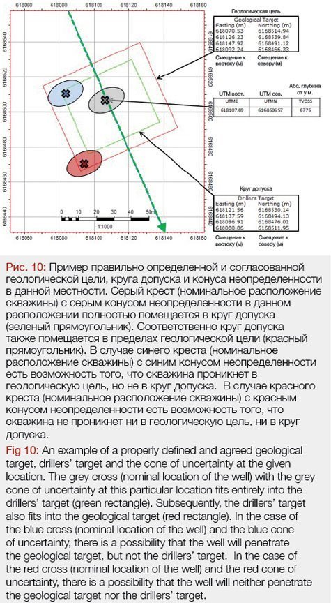

Thus, the uncertainty of the targets and the uncertainty of the position of the well needs to be aligned and synced once superimposed on each other (Figs 10, 11 and 12). Otherwise, there is an increased risk of placing the well outside the target.
Dog Leg severity (DLS) Limitations
Dogleg severity (DLS) is a measure of the amount of change in the inclination and/or azimuth of a borehole, usually expressed in two-dimensional degrees per 100 feet of course length. Notably, this change is measured in three-dimensional space therefore left – right doglegs cause equally harmful side effects.
There are two factors that constitute the DLS measurement, a build rate that measures inclination changes along the vertical plane and a turn rate that measures azimuthal changes in a horizontal plane. It should be noted that DLS is not a simple sum of these two factors. In horizontal and highly deviated wells turn rate values are much smaller in order to obtain similar degree of azimuth change compared to turn values in close to vertical wells. A similar effect will be observed in horizontal sections where the turn rate values are highly inclination dependent.
While some of the doglegs are created intentionally by directional drillers, unanticipated ones have destructive tendencies. High doglegs intensify the overall friction creating fatigue wear and abrasion of drill pipe, casing and completion string and increase the likelihood of getting stuck or not reaching the planned total depth (TD). Consequently, the DLS ranges agreed and imposed prior to drilling operations must be obeyed. Note that it is imperative to “geosteer well on paper” (to conduct GWOP exercise) and verify whether the DLS limitations prevent penetration of all the planned targets (Fig. 13).

For this reason, the DLS will often limit the choice of well paths. Consequently, the DLS limitations significantly impact the process of well landing in a target, building up through the sumps, punching through chert horizons and restrict the possible room for geosteering if a sharp change of inclination is required. In extreme situations, if an excessive dogleg impairs the success of a well, remedial action can be taken, such as reaming or under-reaming through the dogleg location, or even sidetracking.
It must be remembered that the measurement of DLS values obtained by stationary surveys (usually every 100 ft) do not represent a real degree of borehole inclination or azimuthal change. This can only be acquired by instantaneous (continuous) azimuthal and inclination measurement. Therefore, the stationary surveys might not capture some of high doglegs created while drilling and provide only averaged values of the given interval. All possible micro-doglegs that occur in between the stationary surveys are masked.
Planning a Trajectory
Most reservoir sections require simple designs where a well profile of a two-dimensional horizontal section maintains the constant azimuth with only changes of inclination (steering up and down). In other cases, azimuthal changes are planned prior drilling (azimuthal geometrical drilling, semi-three-dimensional geosteering) and are not part of the geosteering strategy. In some extreme cases complex geological settings require full three-dimensional geosteering (steering up, down, left and right). As it is impossible to predict every steering decision at the planning stage, these three-dimensional deviations must be reflected accordingly in the planned trajectory leaving leeway for geosteering decisions (Liu et al., 2004).
Irrespective of the complexity of the planned trajectory, all possible steering decisions and trajectory changes may affect the shape of the trajectory. Since the direction of drilling cannot be verified at the planning stage, the geosteering must act as a contingency for uncertainties of all possible trajectories in which the well might be drilled. Therefore, testing all the possible steering decisions that might jeopardize achieving the desired well path, is required prior to drilling during the GWOP exercise.
A trajectory in the reservoir section is based mainly on provided geological targets with x, y, z coordinates. Since the actual subsurface structure (targeted reservoir location in three-dimensional space) and petrophysical properties of these targets (reservoir fluids, porosity, and permeability) are often different from those indicated by the predrill model, sufficient flexibility must be built into a trajectory to allow for the possibility that the targets could require modification during drilling. This is where active geosteering takes place to adjust the plan to the actual setting.
The worst-case scenario includes a design of a trajectory that is not feasible for geosteering due to directional drilling limitations (e.g. DLS ranges imposed prior to drilling operations and BHA steering limitations). This happens when planned DLS of a trajectory between the targets is on its borderline of achievability (e.g. trajectory with too high DLS between too many targets). In such situations, there is little room to adjust the trajectory and to hit all the targets if their position requires alteration. It is self-evident to adjust trajectory while geosteering, but a significant unforeseen discrepancy from the planned one (azimuthal and inclination, DLS, length, total depth) may put achieving all the objectives and hitting all the targets at risk (Fig. 13).
Three-Dimensional Geosteering
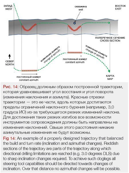
In some directional drilling operations, a target in the reservoir cannot be reached by drilling along a planar two-dimensional well path because of underground obstructions, such as faults or existing well bores. In such extreme conditions, a three-dimensional well trajectory is usually designed. Special care should be taken during due diligence (and GWOP) since changes of azimuth will restrict possibilities of inclination build/drop for any steering BHA (Fig. 14). A balance between these parameters should always be maintained. Depending on a geological environment for which the trajectory is designed, certain confinements are always built into the design (e.g. 3.0 degrees per 100 ft DLS restriction, cumulative azimuthal change along the wellbore not exceeding 90 degrees etc.).
From the geosteering perspective, two-dimensional or close to two-dimensional trajectories with minimal azimuthal changes, are less challenging to drill. The biggest geosteering benefit from such two-dimensional design will be obtained through minimal or no distortion to the projected trajectories represented on cross-sections. This will impact significantly on dip inclination calculations and horizontal and vertical distances resulting in more accurate numbers.
Conclusions
All of the above-mentioned aspects are interconnected and influence one another at different stages of the geosteering process. For instance, a correctly chosen RSS system will allow drilling a required well path and the tool responsiveness to the geosteerers’ command will not be jeopardized by the type of drilled formation. The BHA and its ability to deliver specific dogleg range will directly affect the geosteering performance while drilling, producing desirable on-target trajectories. The actual well trajectory and its deviation from the plan will also be directly affected by well-defined uncertainty envelope ranges for the geological target. Even if the range of uncertainties cannot be minimized, a knowledge of such range can provide mitigating options that prepare for this eventuality. Prior drilling awareness of all the sections where azimuthal changes (turn rate values) will reach the maximum allowed values for DLS, prevent planning an unrealistic BHA performance and reduce the possibility of missing a target. Finally, more robust planning, due diligence and conducting a GWOP exercise will minimize the need for unanticipated sharp inclination or azimuthal changes assuring penetration of all the planned targets.
Therefore, once all the aspects above are considered during the planning stage, they will support the steering decision-making process while drilling and allow for delivering smooth, predictable, optimally placed wellbores. This is the ultimate objective of any geosteering process.
For Part Two of this article click HERE

About the Author
PIOTR PRZYBYLO has acquired crucial technical and business skills that enabled him to drill some of the deepest and longest wells in the world. He bridges the gap between the technical and commercial sides of the upstream oil and gas industry. He is the Founder of GEOMODES, a company that educates future experts in the field of geosteering and optimizes team organizational structure for efficient skill utilization. He is also the author of HORIZONTAL WELL GEOSTEERING GUIDELINES (Amazon)- first ever published comprehensive manual which is a must-have for every geosteering expert.
Reach out to author: piotr.przybylo@geomodes.com
References
• Bond, C.E., Gibbs, A.D., Shipton, Z.K., Jones, S., 2007, “What do you think this is? Conceptual uncertainty in geoscience interpretation”, GSA Today: v. 17, no. 11, 2007
• Griffiths, R. 2009, Well Placement Fundamentals, Schlumberger, ISBN 978-097885304-4
• Liu, X., Liu., R., Sun, M., 2004, “New Techniques Improve Well Planning and Survey Calculation for Rotary-Steerable Drilling”, Presented at the IADC/SPE Asia Pacific Drilling Technology Conference and Exhibition held in Kuala Lumpur, Malaysia, 13-15 September 2004 – IADC/SPE 87976
• Mantle, K., 2013/2014, “The Art of Controlling Wellbore Trajectory” Oilfield Review Winter 2013/2014: 25, no.4.
• Seiler, A., Rivenæs, J.C., Aanonsen S.I., Evensen, G.,2009, “Structural Uncertainty Modelling and Updating by Production Data Integration” Copyright 2009, Society of Petroleum Engineers (prepared for presentation at the 2009 SPE/EAGE Reservoir Characterization and Simulation Conference held in Abu Dhabi, UAE, 19-21 October 2009) – SPE 125352
• Soleng, H. H., Rivenaes, J.C., Gjerde, J., Hollund, K., Holden, L., 2004, “Structural uncertainty modelling and the representation of faults as staircases”, 9th European Conference of the Mathematics of Oil Recovery — Cannes, France, 30 August – 2 September 2004
• Sugiura, J., Hornblower, P., Hawkins, R., Lowdon, R., Olokpo, A., Figueredo, C., 2014, “Continuous inclination, azimuth measurement optimizes RSS control”, May/June issue of Drilling Contractor, 2014
Author: Piotr Przybylo