LUKOIL: First Intelligent Multilateral TAML5 Wells on the V. Filanovsky Field
The first Intelligent multilateral TAML5 wells on the V. Filanovsky Field are a great example of how new technologies are helping to optimize CAPEX, and thanks to a higher productivity index, achieving higher production rates. Multilateral well geometry combined with an ability to monitor and control each leg separately helps to optimize flow patterns, prolongs well life and contributes to a higher cumulative production. The paper focuses on well design, project execution and production results.
To achieve the results, the work was conducted inseveral phases:
1. Choose a well design which would optimise CAPEX and reach production and recovery targets.
2. Perform two trial jobs on an existing mature field to learn about the technology and to prove the concept.
3. Use the experience gained on the trial jobs to optimise the requirements, well design and procedures.
4. Execute the job, control and manage the execution to ensure compliance to the plan.
5. Review the first production results and estimate benefits obtained from the project.
This paper describes all the steps focusing mainly on installation procedure, execution and production results review.
As a result of the work done, LUKOIL successfully installed two first intelligent TAML5 completions on the V. Filanovsky field and achieved ~20%-60% higher production than on nearby single bore wells (up to 38000 bpd). This first wells proved that the contemporary intelligent and multilateral completion technologies are mature enough to deliver consistent results. Production results showed that the actual productivity index matches the predicted results. This proved that intelligent multilateral well design enables many benefits, such as slot preservation, higher productivity indices, faster production buildup and can facilitate reaching higher cumulative production from the field.
The paper describes the introduction of complex intelligent multilateral well design. This practical example can be used for future reference by drilling and production focused petroleum industry professionals to better understand benefits and limitations of existing technologies. Actual production result can also be used as a benchmark for field development planning.
Introduction
There is still a generally accepted opinion, that multilateral wells are risky to drill, that there is no practical point to consider multilateral technologies for real life field development planning. The goal of this paper is to show that multilateral technologies can be successfully applied for practical needs, bringing significant benefits for the project. Specifically, for V. Filanovsky project intelligent TAML5 multilateral wells help to reduce capital investments, maximize production rates and contribute to increase of total recovery.
There are projects, where the whole field is developed with bilateral and trilateral wells. The main driver for multilateral wells is normally a complex reservoir, which cannot be developed efficiently with conventional wells. For example, the Vincent field (Nettleship et al. 2014) is deep water heavy oil reservoir, where conventional wells do not provide sufficient reservoir coverage and productivity, so multilateral wells were used to improve the well productivity index, maintaining capital expenditures at a reasonable level. Another example is the Korchagin field, (Shestov et al. 2015; Ruzhnikov et al. 2016; Eliseev et al. 2016) an oil rim reservoir with active gas cap, which requires strategic well placement and drawdown management to achieve target oil recovery.
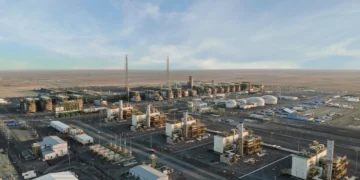
The V. Filanovsky field, where two first intelligent bilateral wells were drilled, is a long anticline trap complicated by series of faults, which divide the reservoir into several semi-connected blocks. The main Lower Cretaceous reservoir contains 4 productive beds, separated from each other. At field development planning stage the V. Filanovsky field’s estimated production rates were ~35000 barrels per day per well, which made this project critical for LUKOIL.
At the beginning of the field development planning, to minimize the number of used slots on the platform, the producing wells were designed as dual laterals. To minimize risks, producers could be drilled as a single bore and then converted to dual laterals. To ensure that the technology is mature enough, two trial jobs were conducted on the nearby Korchagin field (Figure 1). These jobs went smoothly with zero non-productive time related to the multilateral operations. This first success proved the concept of intelligent multilateral wells from both technical and economic standpoint.

The first phase of the V. Filanovsky field development consisted of 6 producers and 2 injectors. 2 wells were planned to be drilled as dual laterals from the start – Well A and Well B.
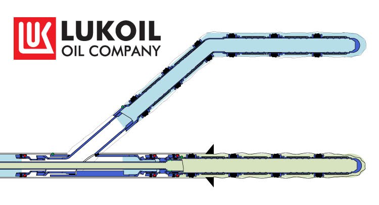
Well’s A and B were designed to drain the same reservoir with two wellbores equipped with sand screens. TAML5 pressure-tight junctions were used to prevent gas coming into casing exit interval in case the sidetrack drilled into a gas-saturated interval. Intelligent completion strings with pressure and temperature gauges and downhole multiposition flow control valves allow the monitoring and control of production from each leg separately. Above the flow control valves the production streams commingle. The main bore liner screens are equipped with closable sleeves, which are designed to be operated through the upper completion.
Execution Case Study
In order to share the practical experience accumulated after drilling 4 dual lateral wells, the sequence of the operations for multilateral well drilling and completion with comments is presented below.

Production Casing Interval
There are a series of considerations with regards to the production casing interval planning. Best practice is to prepare the sidetrack drilling in advance. For the casing joints, where window is intended to be cut, centralizers are installed not on the middle of the joints, but at the top, right below the coupling. Since cement quality is crucial for a successful casing exit, normally the lower parts of the production casing are planned to be cemented with a heavier slurry. To optimize the equivalent circulating density, the bottom section of the casing is placed above reservoir in a stable shale interval. Apart from that, the casing exit points are normally planned to be placed in stable rock intervals, preferably non-permeable, to ensure hydraulic integrity at the junction once it is installed. The casing exit interval has a restricted dog leg severity less than 3⁰/100ft. The contingency sidetrack point is normally chosen two casing joints above the primary one. As a common practice, the main bore liner has 80 meters overlap with the production casing, and the window can be cut ~30 meters above the liner. For Well A this meant that ~130-180 meters at the bottom of production casing has to be placed within a 12 meter-thick layer of shales (Figure 4). And inside this interval 30 -70 meters must be with a dog leg severity less than 3⁰/100ft.

For Well A the project team set up two more requirements. Firstly, the casing exit interval must be not only tangent, but also below a 90⁰ inclination. Considering that the target bed should have inclination of 92-93⁰. The reason for this was there is not much of a track record for window milling in angles above 90⁰. In addition, this tangent section length was 130 meters to provide 6 potential sidetrack points. Second, as per the development plan, the reservoir had to be penetrated at specific coordinates. This means that if the target formation is higher than expected or has a higher inclination, the well cannot be shortened. It must be drilled with inclination ≥90⁰ whithin the target bed to reach target coordinates where the casing TD is planned.
As a result, the well trajectory was quite complex. When the motherbore liner was run later, during the ball pumping to release the running string, losses of 50% were observed. Flow rate was limited and setting the ball did not land the liner running tool as planned. To release the liner running tool, it was necessary to drop a sponge ball which chased the ball to the seat and helped to release running string. In this case the complex well trajectory (Figure 5) caused difficulties with the liner run.

When the next multilateral well (Well B) was planned, all requirements were analyzed and ranged. Requirement for the tangent section length was reduced from 130m to 70m. The risk of sidetracking in inclination more than 90⁰ was rated as non-critical. After these adjustments Well B’s trajectory was significantly smoother (Figure 6) and the liner was run, set and released without complications.
This specific example shows that all the requirements and risks must be considered together, then ranged according to their critical level. The final plan must be a compromise between the overall minimal risk/deviation from the required plan. In this specific case the redundant contingency casing exit points and non-critical trajectory features were sacrificed to simplify the well trajectory and to minimize the risks during liner deployment.
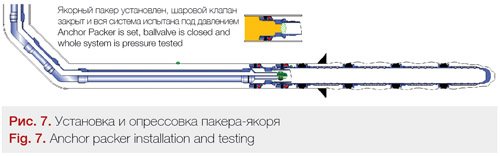
Setting the Anchor Packer with an Isolation Valve and Checking Orientation
Once the first lateral is drilled and completed as usual, multilateral operations start. First step is to set the anchor packer assembly to isolate the main bore and to create a foundation for the window milling and junction installation. The whipstock for the casing exit uses an anchor packer as an anchoring and orienting device, and later the multilateral junction is installed into the same packer.
To adjust the high side orientation of the window, the orientation of the packer can be measured during a separate run. A good alternative to that is to use a slim MWD tool below the packer setting tool, pre-orient the packer into desired high side and then set it.
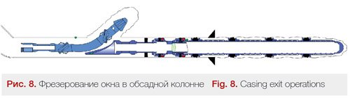
Casing Exit
The window is cut with the use of standard casing exit system, compatible with an anchor packer. Good practices for such operation are torque control and ROP control, especially in lower part of window. The length of the rathole drilled should be be minimized to avoid wellbore washout and trajectory drop.
Lateral Bore Drilling and Completion
In general, the drilling is performed as usual. One important point is – during the POOH section of ~25 meters where liner top is going to be dropped, this is relogged with a logging tool. This caliper log is used to place the liner top in a section with an ID close to nominal, which facilitates the connection of junction and lateral liner later on.

Lateral Liner
The lateral liner is deployed to the planned depth and dropped in the open hole 7-9 meters below the window. Then, when the multilateral junction is being installed, this junction is connected and sealed inside the lateral liner. The important part is – in order to perform the depth of lateral liner has to be known within a 1 meter tolerance.
When a well is drilled, the BHA shows one bottom hole depth, and when the liner is run, the BHA normally goes deeper than the measured bottom hole depth. An important point is that this tally error can be calculated to some extent, but as with any calculations, one cannot be sure they are 100% correct. For multilateral lateral liners this tally error is caused by buckling and casing/drillstring tally differences that can be a problem, as the spacing of the junction elements must be very accurate.
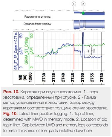
In order to eliminate the liner top depth uncertainty, the lateral liner was run with a MWD, in memory mode, below the standard liner running tool. Pip tags were installed in the liner top connection to be a reference point of the liner. The same pip tag was installed into the whipstock to be a reference point for the mainbore. As a result, operator was able to compare the LWD gamma log and memory gamma log from the liner running tool and measure the actual distance between the pip tags. In addition, the log comparison showed, that in an open hole section the logs coincide. But in the sections, where the tool was inside the liner, the gap between the logs occurred. This gap value corresponds to the thickness of the steel part of the liner. Meaning that not only the distance between pip tags can be measured, but the position of all of the logged liner parts can be seen on either log.
In order to minimize the risk of wellbore collapse, the equivilant circulation density, ECD, must be maintained at all times until the lateral bore is fully cased. This means that if any displacement is planned, th ecompletion fluid must be able to prevent the wellbore collapse. For the Korchagin and Fialnovsky fields the typical completion fluid is CaCl2 brine, which is unable to prevent wellbore collapse, so drilling mud was not displaced in the upper laterals.
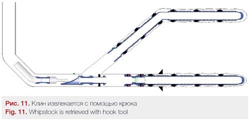
Retrieving Whipstock
The whipstock was retrieved with a standard hook tool, which engages the whipstock and with use of a progressive jarring it retrieves it from the packer. There is a chance of misruns. On Well B the whipstock was not retrieved at the first attempt. The contingency tool, a die collar, was run to catch it. The die collar run was performed with a MWD in the BHA to orient the cut lip guide to the top. The project team believes this decreases the chance of damaging the tool during whipstock engagement. The use of MWD was recognized as a helpful adjustment and was noted as a good practice for future use.
After the whipstock is retrieved it is recommended to run a clean out assembly with magnets to remove metal debris which can damage sealing interfaces of the junctions and/or create mechanical barriers.
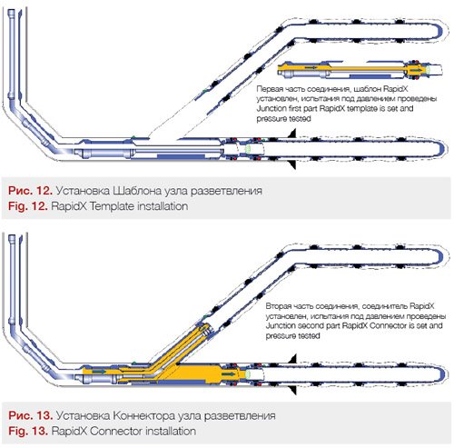
Junction Installation
The junction template is run in on drill pipes, set into the packer, pressure tested and left in hole. In order to ease stinging in, MWD is recommended to be added above the running tool, to show Template orientation in real time.
For the Connector installation the correct spacing out is critical. If all the depths are determined correctly, the installation itself is straightforward: the assembly is run to depth, set into the template, pressure tested and left in the well. In order to minimize the time for orientation, it is recommended to use low-flow MWD in the string above the running tool. Once the Connector is in place, the well is displaced with brine to minimize formation damage.
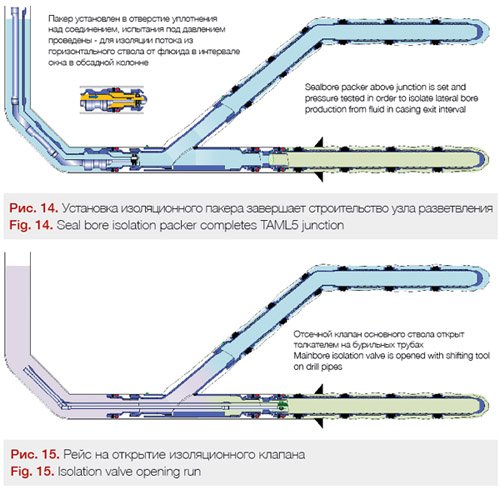
Seal Bore Isolation Packer Setting and Opening Main Bore Access.
Bore sealing isolation packer finishes the TAML5 junction construction. Standard seal bore packers are run on drill pipes, set inside the junction and the sealing interface between the junction and the packer is tested with the use of an inner string. After the pressure test packer is set, pressure tested and left in hole.
Once the packer is installed, the isolation valve is opened by shifting the tool. Normally the main indication of a successful opening is noticeable losses. This operation can be eliminated if a hydraulically activated valve is used.
Intelligent Completion String
Intelligent completion installation is conducted in a fully cased well. The completion string lands into the polished bore below the junction. All 4 installations have been performed without incidents on the project.
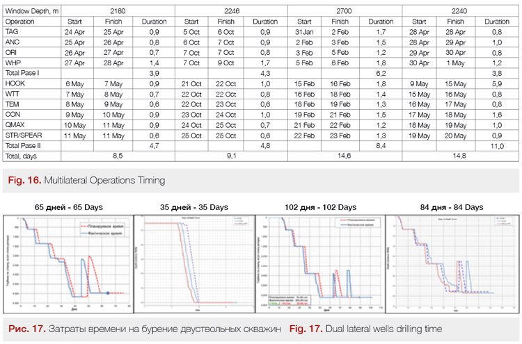
Drilling and Completions Timing
It is always an important question – how long it takes to drill and complete a multilateral well vs usual one. As you can see at the Figure 16, the extra operations specific to a multilateral junction are taking from 9 to 15 days. The whole well drilling time can vary from 35 days for a reentry multilateral to 105 days on new wells depending on laterals lengths and junctions depth (Figure 17).
Production Results
Well A
Well A Production started in February 2017. Before production started a cleanout procedure was performed, in a lateral-by-lateral manner. In highly-permeable formation conditions and with a fully prepared oil-based mud the cleanup process is not a small, trivial task especially without flow control valves for each lateral. The operator should control cleanup rates and drawdowns in order to sustain sufficient mud velocity in the horizontal section, of each lateral, to prevent fluid slippage. However, with the help of intelligent flow control valves and a detailed cleanup procedure, the planed operations were performed successfully.
Each lateral was tested with different surface chokes as well as with a constant surface choke and different downhole flow control valves chokes. Productivity Indices for each lateral were obtained and optimum production conditions were agreed. The lateral drawdowns were estimated in around 10 bars each and initial rate reached 38,000 barrels of oil per day.
Since multilateral junctions have complex geometry – it normally chokes the upper lateral with 3-4 bars more than the lower one. This difference in pressure drops is managed by flow control valves position adjustment. As a result, production from both laterals was balanced to distribute flow in a more uniform manner.
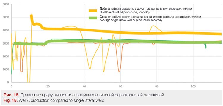
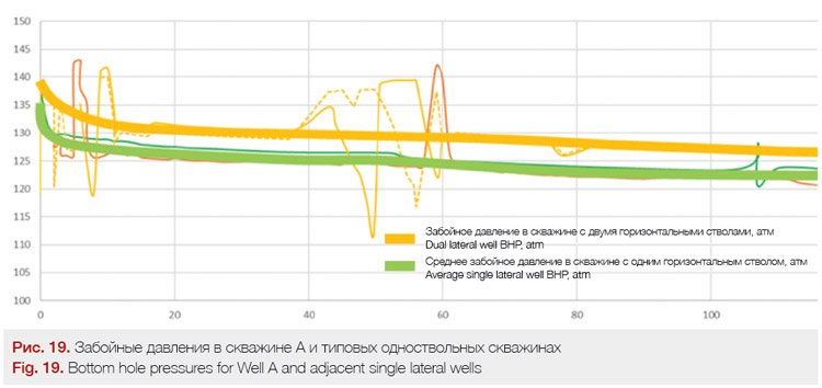
Production trends are similar to conventional horizontal wells – high production rates at the beginning and slow rate declines due to reservoir pressure decline together with a gas-oil ratio increase. As of today, the first multilateral well is the best producer on the field, with a current oil production rate of more than 28,000 barrels of oil per day. The average horizontal singlebore producer has a rate of less than 18000 barrels of oil per day.
Comparing the production behavior of a dual-lateral well with a conventional horizontal well on the field we can point to an oil production increase factor of 1.2-1.6 depending on the applied drawdown. Well A’s BHP is higher than on single bore wells. Potentially, the flow rate from the dual lateral well could be higher, but it is limited by drawdown caused by the friction associated with the production tubing and a minimum wellhead pressure restriction. It can be concluded that Well A gives more production at lower drawdown.
Well B
Well B has an interesting background. When the second lateral was drilled, the LWD (logging while drilling) tool showed the indication of a possible gas presence in the reservoir section, who’s vertical depth was significantly lower than the predicted gas-oil contact. One of the reasons for that could be that dissolved gas came out of the solution due to a pressure drop around working well. However, after a successful well clean-up and during the well multi-choke testing, the upper lateral produced oil with a high GOR (gas-oil ratio).
The project team reviewed the seismic data, logs and production data results and came to the conclusion, that the lateral was drilled between two sealing faults with small local gas cap.
With the help of a downhole multi-positional valve, the production from the upper lateral was choked and the well’s oil production was optimized. Currently the oil production rate is about 23000 barrels of oil per day with a GOR of 250 m3/m3. This compares to a typical well’s GOR of about 150m3\m3. This high oil rate with a relatively small gas-oil ratio allows the well to be compared to average industry gas wells by produced gas volumes. It should be noticed, that without downhole flow control valves and an ability to choke the lateral bore, the overall well oil production would be much lower. The production strategy for the second well is to maximize the oil production from the mainbore and to control the gas\oil production from the lateral bore.
The wells were successfully linked into the real-time production monitoring & optimization software for intelligent wells on the V. Filanovsky field. The key parameters such as tubing and annulus pressures, downhole temperatures, calculated production and laterals drawdowns are monitored and analyzed by an operator in real-time. Once the need for the well’s production parameters adjustment is confirmed, the downhole flow control valves can be switched within 1-2 hours, without any significant expenses for the operator.
The current production strategy on the field is focused on maximizing oil production in the foreseeable future. Two water injector wells are planned to be drilled to maintain reservoir pressure. Intelligent dual lateral wells increased the reservoir contact area and drained the reservoir in more uniform manner, which is expected to facilitate higher ultimate recovery.
Discussion
Intelligent multilateral wells are a handy tool, ready to be used in a variety of projects. Specifically on offshore projects once initial drilling phase is complete, sidetracks are the optimal way to keep production at a required level with minimum cost.
For LUKOIL dual lateral wells were a proven and important technology. Currently, at the field development planning level, all the wells are planned in a way to allow future drilling of second legs with TAML3 or TAML5 multilateral junctions.
Intelligent multilateral wells help to achieve faster production buildup and reduce the capital expenditures of the project. Slot preservation enables the operator to keep drilling from existing platform instead of building additional ones. The upper well sections costs saving can be significant as well. Downhole multiposition flow control valves help to overcome uncertainties such as an undesirable fluid production by one of the legs.
Conclusions
1. Up to today, LUKOIL has already drilled 4 intelligent dual lateral wells. All of them were drilled successfully and achieved their technical goals. This shows intelligent multilaterals are a reliable mature technology which are applicable in high profile projects. (Figure 17). The industry has has a sufficient track record and experience to stop considering multilateral wells as a cost-prohibitive high-risk undertaking. The economic benefits are obvious, the risks are known and manageable.
2. The time spent drilling the extra lateral on the project is about 30 days (Figure 17). This time is consistent with other projects around the world (Nettleship et al. 2014)
3. The Production results show that, compared to similar horizontal multilaterals, resulst in 20%-60% more production at lower drawdowns (Figure 18, Figure 19). This result is consistent with theoretical practisces (Salas et al 2016).
4. The ability to control production from each leg separately maximizes the cleanup efficiency, eliminates the need for costly workover operations and allows the management of the reservoir to maximize daily and cumulative oil production. Specifically for Well B (p.11), the intelligent downhole control has helped to overcome potential severe early gas breakthrough, caused by an unexpected penetration of local gas pool by the second lateral.
Authors
Mikhail Yurievich Golenkin: «LUKOIL-Nizhnevolzhskneft» LLC
Artur Latypov, Sergei Shestov, Igor Bulygin, Azat Khakmedov: Schlumberger
Acknowledgement
The authors would like to thank LUKOIL and Schlumberger, who kindly allowed this material to be published.
References
1. Nettleship, G., Palmer, A., & Eshtewi, A. (2014, June 1). Installation of Complex Multilateral Wells With Standalone Sand Screens in the Vincent Field. Society of Petroleum Engineers. doi:10.2118/169903-PA
2. Shestov, S., Golenkin, M., Senkov, A., Blekhman, V., Gottumukkala, V., & Bulygin, I. (2015, October 26). Real-Time Production Optimization of an Intelligent Well Offshore, Caspian Sea. Society of Petroleum Engineers. doi:10.2118/176648-MS
3. Salas, J. R., Clifford, P. J., & Jenkins, D. P. (1996, January 1). Multilateral Well Performance Prediction. Society of Petroleum Engineers.
doi:10.2118/35711-MS
4. Ruzhnikov, A., Latypov, A., Dubovik, A., & Zvyagin, V. (2016, October 24). TAML-5 Intelligent ERD Offshore Well: A Case Story of Successful Application in the North Caspian. Society of Petroleum Engineers. doi:10.2118/181927-MS
5. Eliseev, D., Golenkin, M., Senkov, A., Latypov, A., Bulygin, I., Ruzhnikov, A., … Kashlev, A. (2016, October 24). New Vision: IC TAML5 Wells on Caspian Offshore. Reasons, Implementation and Results. Society of Petroleum Engineers.
doi:10.2118/181901-MS