New Achievements in Multilateral Drilling and Completions in Western Siberia, Part 2

Engineering and Multilateral Drilling and Construction of ERD Wells at the Yurkhar OGCF
Drilling Mud
Oil-based mud (OBM) was successfully used at the Yurkhar OGCF as well as within the wells being considered in this article. Below is the list of their advantages, which enabled the re-placement of traditional, regional, drilling-mud systems with OBM:
• High wellbore stability
• High-quality initial penetration
• Prevention of differential sticking
• Friction ratio reduction
• Improved reliability of the BHA components.
But, at the same time, a new oil-based drilling-mud (OBM) system was applied to the wells under consideration; this system provided superior performance allowing the successful conclu-sion of drilling program.
As the classic oil-based mud has the rheological properties that take on a wide range of values under different temperature conditions, thus the equivalent circulating density (ECD) will also take on a wider range of values. For this reason, the new chemicals were added into the mud composition to enable a more stable profile of rheological properties of the drilling mud. The mud, with these properties, allowed the wells to be drilled under complicated geological conditions. The major modifications of the mud’s composition included the use of a developed set of emulsifiers and a new rheology-modifier to ensure the stable growth of rheological properties through the temperature reduction range.
Based on the past experience and project data, the following goals were set to provide a trouble-free ERD well drilling program:
• Keeping the ECD within a safe operating range
• Minimizing the risks of collapses in non-stable sections, the differential sticking risk, and the risk of mud loss in highly permeable formations
• Improving the quality of wellbore cleanout and removal of drill cuttings from the upper sections
• Minimizing the risks of mud loss while casing the wellbore
• Reducing the friction ratio
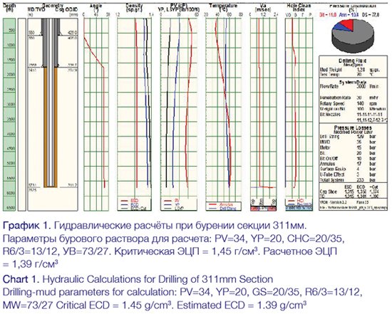
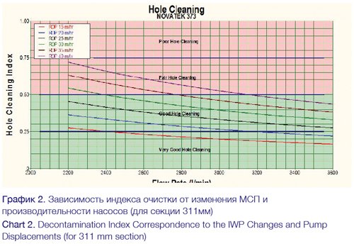
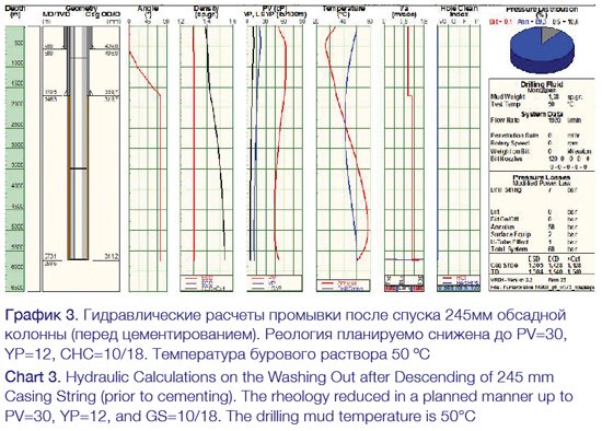
Whilst constructing the section for production-casing and the tie-back strings, the main complications related to the wellbore’s instability in the Pokur suite and top of BU-group formations, as well as to the risks of drilling mud loss. Prior to execution, a well cleanout model was built using the hydraulic calculations carried out with a special software package (charts No. 1-3, calculations relate to the sections below the operational string, and similar calculations were per-formed for each of the sections), as well as the rheological properties of drilling mud and modes were matched to the maximum allowed value of the ECD: it is apparent from the charts that the estimated ECD is not above the maximum allowed value (the maximum allowed ECD is 1.45 g/cm3).
During the real-time upgrade of the geotechnical model, the data was refined with the drill-ing-mud pressure gradient constrains, under which the wellbore stability will be protected from both collapses and fracturing, as well as from formation-fluid flow into the well. In terms of well-bore stability, the planned drilling azimuths were not the safest. Therefore, to ensure the trouble free operations while drilling, additional factors are required in order to provide the acceptable values of the equivalent circulating density measured while drilling.
The continuous monitoring of the equivalent circulating density (ECD) as well as the rheo-logical parameters of the drilling mud, updated and recalculated tripping rates and drill-ing/cleanout/reaming modes based on the recommendations from the geomechanics engineers, enabled the construction of well under the complicated geological conditions requiring a strict ob-servance of all the parameters within narrow range of allowed values. Additionally, a real-time application and updating of the geomechanics allows for the optimization of the drilling mud.
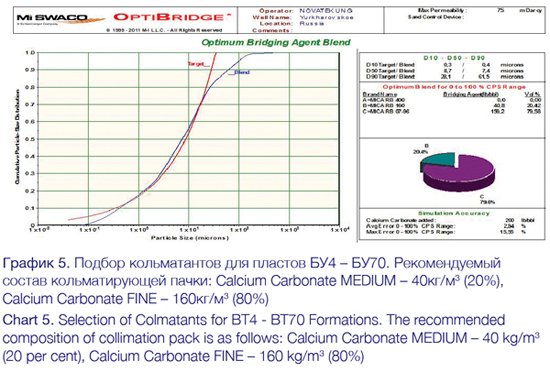
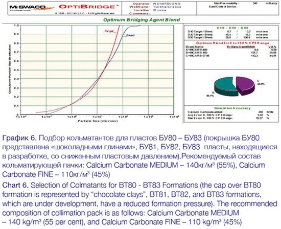
If there were signs of wellbore instability (pressure spikes, increase of torque/uneven drillstring rotation, increased weight on bit, and occurrence of caved cuttings on the screens), the additional cleanouts with circulating bridging agents were performed, as well as the penetration rate and drillstring speed were subjected to limitations during the cleanouts. These measures enabled a trouble-free drilling of this section.
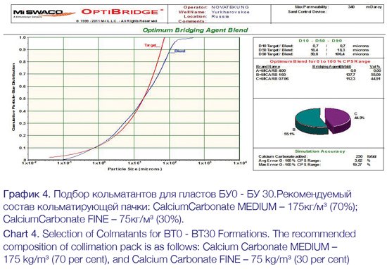
The technological operations on circulation of bridging agents allowed the reduction of seepages and loss risks. The optimal fractional composition of bridging agents was blended with special software (charts No. 4-6). The chart shows that the calculations applied
to blend the fractional composition are in full concordance with the data received and they
overlap the target values.
While drilling the wells on the Yurkhar OGCF, the most significant by both frequency and volume of losses was the lost circulation from the cleanouts performed before or during the casing cementing. This lost circulation has some peculiarities compared to the drilling conditions. The small annular gap significantly increases the equivalent circular density and therefore, increases the probability of fracturing. While the casing string is lowered, the drilling mud lost circulation treatment is hindered. Meanwhile, the lost circulation implies not only the drilling mud loss, but it reduces the likelihood of a successful casing-string cement job.
One of the preventive measures for reduction of lost circulation probability when casing, is an application of Integrated Borehole Strengthening Solution (i-BOSS) technology. This technology implies the blending of special-purpose bridging agents and their compounds on a basis of the Poisson’s ratio and Young’s modulus values. If the rock stresses (caused by drilling mud circulation pressure) exceed the elastic deformation values, the micro fractures appear in the rock. In case of a properly blended bridging agent, the agent bridges across the fractures and does not let them to close up when the stresses have been released. In such case, the rock stresses become higher than they were before the appearance of fractures. As a result, the fracture gradient pressure increases.
Before running the casing string into the open borehole, an i-BOSS bridging agent was pumped and the optimal formula of grouting mixtures (spacer and cement mortar) were defined enabling the absence of losses during the cementing.
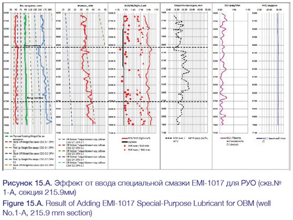
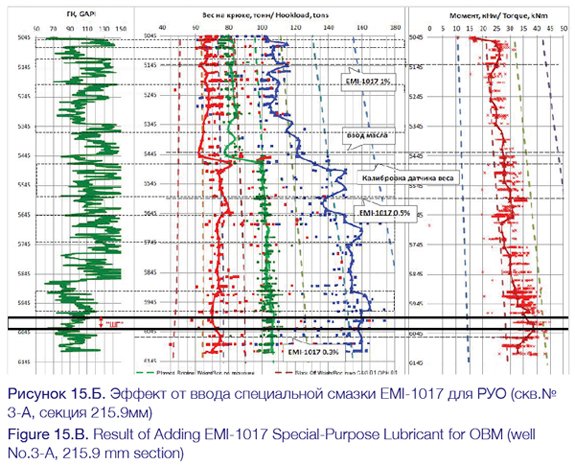
When drilling a section for the tie-back string and the liner, a special-purpose lubricating additive was included to the oil-based mud, which was successfully applied. This additive allowed for a significant reduction in the friction ratio, which is confirmed by the reduction of torque (see Figures 15.A – 15.B – No. 1-A and 3-A), an improvement in the rotation of the drillstring, decrease in vibration, increase of IWP, and improvement in application of the weight on bit.
Wellbore Cleanout
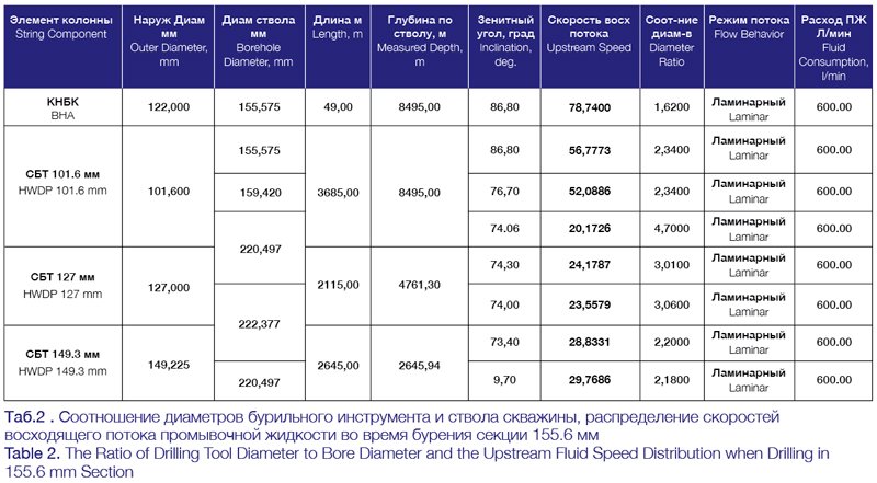
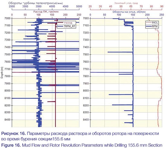
Cleaning the wellbore while drilling the liner section was a major challenge because of the significant drop in fluid consumption, which in turn is used, to ensure a safe range of ECD. As regards to the open hole section, the ratio between the tool diameter and wellbore diameter, or ra-ther between their cross-section areas (PHAR), was 2.34, and for the upper cased sections above the 178 mm tie-back string it ranged from 2.18 to 4.7 (Table No. 2), the drilling mud flow rate throughout the whole 155.6 mm section was 600 l/min (160 gal/min) (see Figure 16), while the upstream fluid speed ranged from 20.2 to 57 m/min (Table No. 2). These terms provide a clear picture of a complicated cleanout of wellbore in the «large-diameter» sections, which is conditioned by the need to reduce the equivalent circulating density ranges.
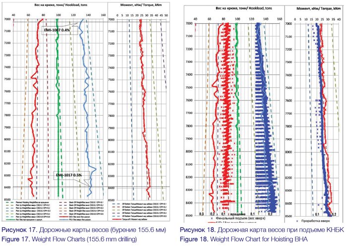
The development of a wellbore cleanout strategy, as well as the patient and precise ad-herence to this strategy including; careful monitoring of the friction ratios in the wells compared to the flow-charts (see Figures 17 and 18), the use of oil-based mud with specially blended formulas, and timely recommendations provided during drilling and tripping operations, have enabled a successful and trouble-free drilling of the horizontal sections, as well as running the liner without rotation in all the wells in the project through to the possible and significant challenges related to the cleanout of the wellbores.
Lining with Casing
The successful running of the production casing strings to the planned depths required the implementation of the most up-to-date solutions available in the industry. The preliminary calculations suggested that the traditional lowering modes can be successful, subject to numerous factors such as the quality of wellbore (adherence to the path, absence of doglegs), cleanouts of the drill cuttings, and the use of centralizers. To facilitate the running of the production string to a depth of 5626 m, the following set of technological solutions were proposed at the planning stage:
• Running the string with rotation and circulation – a special device enables not only the spinning-up of pipes, but also the rotation of pipes (with simultaneous cleanout) when running is hampered
• Automated elevator and links
• Special composite casing-string centralizers allowing the significant friction reduction whilst running the casing (to 0.15-0.20)
• TesTORK™ wireless system to measure the torque and torsion angles
• Pipes with premium threaded junctions to ensure the running of the 244.5 mm heavy casing string with rotation
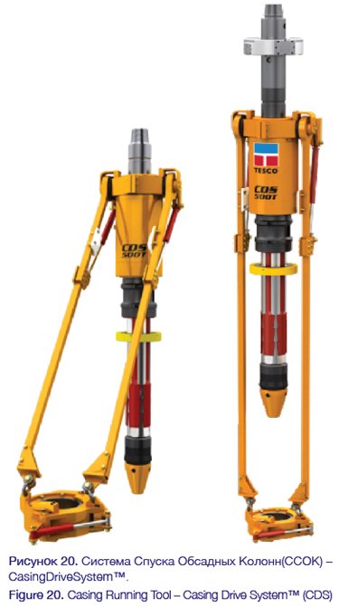
A hydraulically-activated device is used to lower the casing string with rotation (see Figure 20). During the operation, the device should be installed into the casing pipe and packed off forming a tight bond, which allows:
• Casing-pipe twisting
• String pulling and pushing (reciprocating)
• String rotation
• Cleanout
• Combining the afore-mentioned operations if required
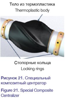
A special composite centralizer (see Figure 21) provides a decreased friction ratio, when contacting the borehole walls, which considerably increases the successfulness of running the casing-string into the planned ERD-wellbore bottom [10]. The centralizer is made of a durable material ensuring the proper centralization of a casing string in order to provide a high quality of cementing operations. Its ellipsoid shape enables smooth drilling in the tight-spot and cutting-bed sections.
The features of special centralizers are as follows:
• Low friction ratio
• Exploitable at temperatures from -40°C to +245°C
• Chemically stable
• Easy to use – low weight
• Usable for casing strings, liners, and filters
• Ergonomic design facilitating the circulation of drilling mud and cement mortar, and reducing the ECD thereby
• Rotatable
Overall 378 centralizers were placed into well No. 1-A, and 342 centralizers – into well No. 3-A.
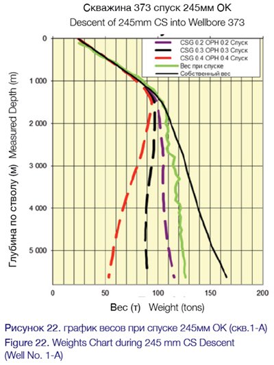
The thorough preparation of the wellbore and the application of the above-mentioned technologies enabled a successful running of the 244.5 mm casing string. Besides, as no rotation of the casing string was required whilst running (see Figure 22 – Weight Chart during Descent), while the hookload reserve was more than 100 tons.
The cement mixtures specifically designed for the Yurkhar OGCF contained special-purpose additives which were used during the ERD-well construction:
• To counteract the gas migration – gas blockers
• To prevent the cement loss – bridging agents
The special formula of spacers ensured an effective clean-out of the oil-based mud, due to:
• Reduced interphase stresses
• Liquefied oil basis for the drilling mud
• Decreased viscosity ratio at the interphase boundary
• Modified wetting properties of the string and formation surfaces – from hydrophobic to hydrophilic
The cementing of the production strings of the ERD wells was performed in one step with raising** DON’T LIKE THIS TERM the cement to the wellhead. While preparing the string centering design, it was succeeded to raise the eccentricity ratio to over 80-85 per cent in the most important sections (target formation, problem areas, and drift angle buildup sections) and to at least 70 per cent in the open-hole section. The absence of annular oil and water production is an indication of the uniform distribution of cement in the borehole annulus and the achievement of the laboratory testing parameters of the cement’s compressing strength.
Special Equipment for the Tie-Back String and for Running the Liner
A reaming shoe was applied to drill in the unstable clay section whilst running the tie-back string (see Figure 23).
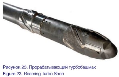
• This equipment includes a torpedo-shaped casing shoe with a special hydraulic rotary drive;
• The calibrator-shoe provides the wellbore reaming whilst running the casing string/liner with circulation, while the string itself is not rotating.
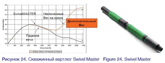
A borehole swivel (see Figure 24) was successfully used to descend the liner into the well No. 1-A.
• Significant increase in the application of load to the liner (reduction of the so-called «buck-ling» effect – lowered risk of tool jackknifing)
• Descent of liner with rotation of the transportation string
• The liner itself is not rotating
Geo-Steering in the Target Horizon
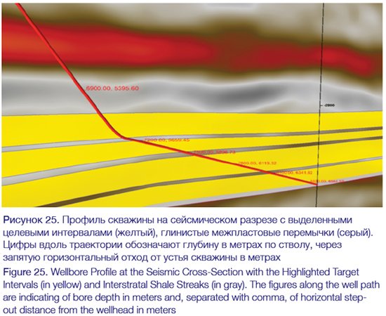
Construction of these wells is complicated by an availability of various geological ambigui-ties occasioned by insufficient information about structural and lithologic fabrics. Deposits are represented by the discrete reservoir sandy rock beds separated with the massive shale streaks (see Figure 25).
As the deposits are localized at a deep depth, there is uncertainty regarding the position of productive bed boundaries. If the horizontal ERD wells are significantly remote from the drilled exploration wells, an uncertainty appears in behavior of structure, which can be conditioned by the local structural or stratigraphic processes. When drilling the ERD wells, the need for reference to stratigraphic markers is particularly topical because of increase of the probable aggregate errors in the MWD inclination measurements (so-called ellipse of errors), which can total tens of meters for such wells.
Under the specified conditions, it seems to be insufficient to provide the simple geometric approach and there is a need for application of the comprehensive approach to the well-drilling operations, which requires a use of the full range of geo-steering techniques. Application of full set of surveys for geo-steering during the multiple intersection proved its relevance during the construction of record ERD-wells in the mainland Russia.
For optimal placement of horizontal bore of the extended-reach wells on the Yurkhar field, a set of logs was used when drilling (a gamma-ray logging, resistivity, density and neutron porosity), which enabled a reliable real-time assessment of the porosity and permeability properties (PPP) of penetrated section. Thereby, it succeeded to optimize the costs by elimination of a need for repeated geophysical surveys in the open wellbore after drilling, which also reduced the risk of complications associated with the stability of wellbore rocks during the overwriting. The assessment of structural features was carried out on a basis of interpretation of azimuthal measurements (density image).
The target production horizon is associated with the sediments of the Valanzhin OGC of the Tangalov suite. The suite consists of the alternating beds of sandstone, siltstone and mudstone. An optimal wellbore drilling strategy was developed to solve the multiple productive for-mation intersection task, which implies a more abrupt drilling in the shale streaks and shale-out zones between the productive sections, as well as the subsequent landing in the sections of the best reservoir properties. Beside of the geological challenges, this strategy optimized the wellbore profile in order to reduce the risks associated with the clay rock stability, which could lead to the technological complications.
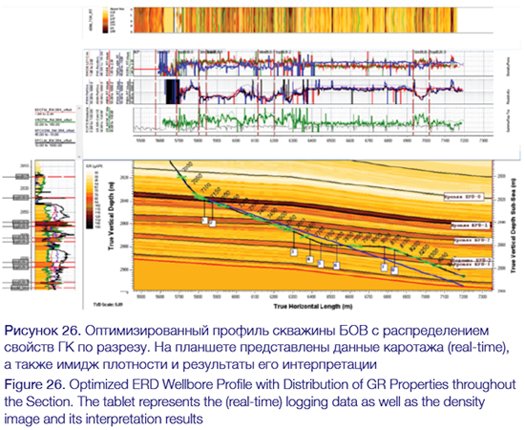
Continuous correlation of the drilled section and definition of the wellbore position relative to stratigraphic markers were carried out on a basis of the incoming real-time GIS data (GR log, electrical resistivity, neutron density log). In accordance with the density image interpretation, the local bedding angles were defined enabling the refinement of structural model. This set of studies proved its effectiveness for such structure of deposit, especially when penetrating the shale streaks between productive sections, the contrasted density allowed the assessment of bedding angles with a high confidence. The information on structural bedding allowed the calculation of stratigraphic thickness of penetrating beds and the forecast of its changes in the azimuth of drilling. This set of information enabled the timely adjustments to the planned path when drilling, which allowed the optimization of profile for both execution of geological tasks and reduction of technological risks (see Figure 26).
The adjustments to the planned path in the horizontal section of wellbore were caused by the significant changes of vertical bed thickness (from 2.5 to 12 m), the structural features in the azimuth of drilling (varying by +/- 2.5 deg.), and the lateral unevenness of reservoir properties.
During the geo-steering, a significant structural and local variability was revealed in the azimuth of drilling (see Figure 27). However, the applied set of incoming real-time GIS data for geo-steering purposes allowed the reduction of encountered uncertainty impact on the achievement of geological targets. Based on the interpretation of azimuthal measurements, the timely adjustments of the path were performed to optimize the wellbore position in the section of the best reservoir PPP specified during the drilling operations.
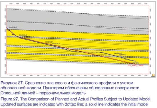
Due to the developed comprehensive approach to the geo-steering program, the effective length of borehole within the productive reservoirs was increased compared to the planned length. The analysis of azimuthal data (image) during drilling operations decreased the structural uncertainty and allowed the reduction of penetration into the shale sections by 14 per cent at the average, as well as the maximization of penetration in the section of the best reservoir PPP.
For the first time in the mainland Russia, an advanced Acoustic Logging was applied during the drilling operations at the well construction on the Yurkhar field. Before proceeding to the project implementation, the petrophysicists of the GIS interpretation team performed the preparation and planning activities based on the data on neighboring wells provided by the Customer.
These data allowed the selection of optimal parameters for Acoustic Logging to obtain both the reliable real-time data and the data stored in device memory.
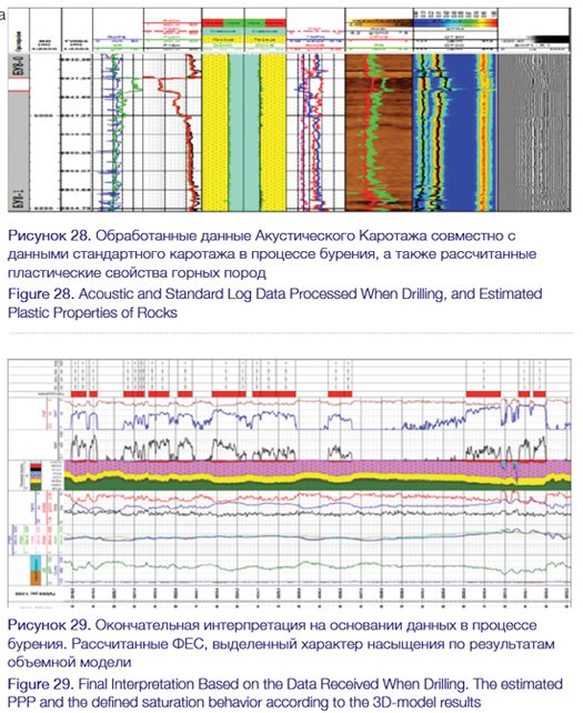
The team of petrophysicists carried out 24-hour monitoring and real-time data processing when drilling (see Figure 28), as well as provided a support to the geomechanics team. Upon the completion of drilling works, the data stored in the AL device memory were processed by the GIS interpretation team. The set of acoustic logs maintained when drilling, along with the standard set of logs maintained during the drilling operations, allowed the solution of geomechanics tasks, such as: the calculation of mechanical properties of rocks and the real-time update of wellbore stability model.
A quantitative interpretation was carried out on a basis of the GIS data obtained from device memory (GR log, electrical resistivity, neutron density log, photoelectric factor) as well as the data provided by the customer (core data, reserve calculation data).
A petrophysical model was built on a basis of the data logged when drilling, by applying a systematical approach in order to solve the set of linear and nonlinear petrophysical equations simultaneously. These equations represent the readings of corresponding geophysical tools con-ditioned by the cubic content of component model (minerals, fluids) and its petrophysical properties (parameters).
Based on a petrophysical cubic model, the basic porosity and permeability properties were estimated, the formation lithology was refined, and the saturation behavior of reservoirs was defined as well.
The petrophysical interpretation (see Figure 29) enabled an estimation of effective length of borehole in the productive reservoirs and showed the success of comprehensive approach to the geosteering.
Record Multilateral Well
The multilateral drilling and completion is a well-known way to increase gas and oil recovery, which is common practice nowadays. A wellbore with multilateral wells – sidetracks – reduces the total costs, increases the productivity, and improves the production of the reservoir. The acceptance of this technology grows year on year, as this type of well increases the recoverable reserves and facilitates the field’s management during production. However, it is worthy to note that the complex well construction is a difficult and risk-bearing task. But the latest advancements and system development increasingly convince the producers that the positives outweigh the negatives. When drilling the wells with a large volume of waste this approach becomes even more profitable through the associated risks increase as well.
The well No. 3-A of the Yurkhar field was planned [11] as a bilateral wellbore with a TAML Level 3 completion.
The definition of the TAML level for the multilateral completion is a key criterion for the planning of multilaterals wells. The TAML level of the multilateral completion shall be defined on a basis of the operator’s aims and objectives regarding the multilateral well (operation, maintenance, possible installation of bilateral completion systems, etc.) During the joint meeting, the TAML Level 3 completion (mechanical support of lateral junction) was selected for the completion of well No. 3-A of the Yurkhar field.
According to the planned path, the sidetrack would be of 1336 m in length. In order to decrease the possible risks during the running of the liner and the subsequent installation of a multi-lateral completion system, it was decided to apply a two-sectional design of lateral liner. The first and the longest section of the liner shall be run separately from the multilateral completion system, by use of installation tool allowing the rotation of assembly during the run, if necessary. According to the completion design, this liner section shall be run 12 meters below the window cut in the string and shall be composed of the well screens and plug-ended liner pipes.
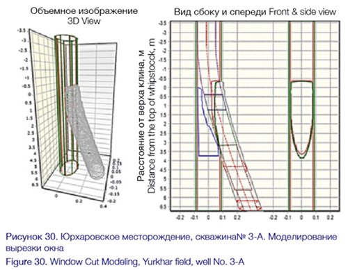
According to the completion design, the second section of liner represents a TAML Level 3 multilateral completion system with a short-liner section to join the first section of the lateral liner. Successful and faultless sidetracking is a key factor that pre-determines the overall success of the project on construction of the bilateral extended-reach well. Comprehensive surveys and analysis were carried out. In order to analyze the operation of the assembly, the real time patented engineering software for the simulation of the window cutting was used to define the following parameters:
• Define the window geometry in the cut and kickoff section
• Estimate the size and shape of the cut section formed by the whipstock
• Forecast the annular trajectory
• Calculate the drift angle and equivalent DSL for the subsequent drilling assemblies running through the kickoff section
• Calculate the drift angle and equivalent DLS for a liner running through the kickoff section
• Estimate the volume and mass of milled metal in the casing string
• Analyze the forces and loads affecting the drillstring and the liner assembly when running through the kickoff section

The above-mentioned analysis of the window cutting and kickoff operations was conducted in order to understand how the full-size window can be milled in a 178 mm string with a high inclination and within over 6000 m of extended reach. Besides, it shall be stressed once again that cutting the window in a 178 mm tie-back string (the top of the tie-back string hanger is installed at a depth of 4541 m, and the window cutting section is between 6054 to 6059 m). Thereby, the whipstock completed with a cutting mill layout was run through the tie-back string hanger and the window has been cut at a global record depth. Because of the same structural features, it was required to select a whipstock completed with a hydraulically-activated anchor and packer as well as with a detachment, as the mechanical anchor requires a supply of load for activation which is impossible, as per calculations, at a depth of 6054 m (with about 5 kilometers of horizontal displacement) and with use of 101.6 mm drilling tool.
Another stringent condition was to provide the low DLS in the window and kickoff section in order to install a TAML 3 Level completion system ensuring the tightness of its junctions. In addition, the modeling ensured that the DLS in the window section has no negative impact on the subsequent drilling and completion assemblies.
Another important issue and challenge was to understand the behavior of BHA during sidetracking, particularly its dynamics.
The suggested system can be configured to operate under any conditions in order to enable high-quality and rapid cutting and sidetracking. Such tracking system enables an execution of tasks in the steel casing strings. Premium class cutters provide a high quality of tracking opera-tions in all the available types of casing strings, including the strings made of high-grade steel and chrome-plated, in any formation, including the most challenging, with a compressive strength up to 275 MPa.
The past experience of similar operations performed in the larger diameter strings, coupled with the technical analysis and modeling, facilitated the designing of sidetracking system and the decision-making on the feasibility of a successful program at a depth of over 6000 m with achieving all the goals in one tripping operation. The cutting simulation software proved that a full-size window can be milled under a 77° inclination, at a depth of 6055 to 6059 m (19865-19880 ft) with spudding-in a 5 m hole; that the DLS in the kickoff section will not affect the subsequent drilling and completion strings. The low DLS values in the casing exit section were in compliance with the stringent requirements applied by a TAML 3 Level completion system, therewith ensuring the tightness of its junctions.
In addition to the above, the compatibility of multilateral well completion system completed with a window-cutting system was tested in order to reduce the risks during the installation of the TAML 3 system under the production conditions at Novy Urengoy. After the Customer provided the casing pipes, the technological window model was created. The window dimensions were taken from the report on modeling the cutting operations. To validate an accuracy of the window’s shape, the weight of model’s metal cuttings was compared with the estimated weight. As a result, there was a complete conformity between the estimated and actual weights. The compatibility test confirmed that the TrackmasterPlus window-cutting system is fully compatible with the RapidTie-back multilateral completion system.
The use of MWD equipment enabled a successful and accurate determination of the attitude of the window cut layout at a depth of 6051.5 m. The window was milled in one tripping operation in concordance with the window-cutting flow chart. After the hoisting of the triple cutter assembly, the cutter component wear was assessed. The assessed wear was within the tolerance range. After finishing the sidetracking, the first liner section was successfully run in, and then, the whipstock was extracted (using a MWD assembly). It was successfully extracted from the well by one tripping operation. Then, the running operations were performed with regard to the second lateral liner section.
A distinctive feature of the TAML 3 multilateral completion system is the definition of technological window bottom. The operation described above is a key for the determination of attitude of the “lateral module” of TAML 3 multilateral completion system within the well. In case of the incorrect attitude of «lateral module», the customer will not be able to access the main borehole.
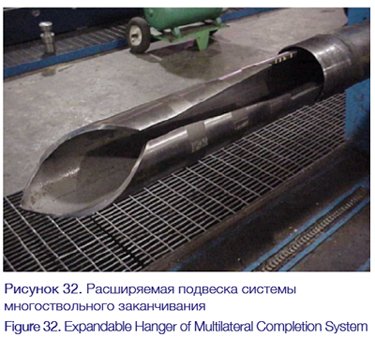
It is important to note that the TAML 3 completion systems used in the industry nowadays should be installed by hanging the «lateral module» to the bottom of technological window. The completion system used at the well No. 3-A includes an expandable «lateral module LINER?» hanger, so it does not depend on a shape of the window bottom. The expandable hanger has the maximum possible drift diameter amongst those that are available in the market of TAML 3 multilateral completion systems, due to the absence of hydraulic cylinders on the equipment to be installed into the well.
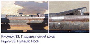
After the correct determination of attitude of the «lateral module» relative to the window, the expandable «lateral module» hanger shall be installed at the top of the multilateral completion as-sembly that hangs the «lateral module» in the casing string. To provide the «lateral module» positioning relative to the technological window, a hydraulically-activated hook was used at the well No. 3-A, enabling the correct determination of attitude by discharging the window bottom (see Figure 33). In case of the extended-reach wells, the planned shape of window often differs from the actual shape of window after cutting, being characterized by a significant lengthwise expansion of the window. The use of an expandable liner hanger and hydraulically-activated hook allows the sytems to remain connected irrespective of the shape of the window when installing the system.
To operate the ERD wells, a multilateral completion system, which uses the technical solu-tions specific to the installation of a TAML 3 system and combining a hydraulically-activated hook and an expandable liner hanger, was developed and successfully applied at the well No. 3-A.
Conclusions
The assessment of the engineering and organizational decisions and achievements proves the relevance of a comprehensive approach to the establishment of a drilling system, as well as the close cooperation between all parties during the well’s construction. Taken together, they are the key factors in successfully implementing technically complicated projects, such as the world-class ERD wells successfully drilled on the Yurkhar field in the Yamal region.
The selected technologies and their combination into the drilling system is an economically feasible solution for the field’s development, taking into consideration both regional particularities and the existing traditional technological constraints.
The successful drilling of three wellbores with an extra-long horizontal reach at the Yurkhar field became a result of wise decisions made on a basis of experience accumulated by the engineers and specialists of NOVATEK OJSC, NOVATEK-YURHAROVNEFTEGAZ LLC and Investgeoservice CJSC coupled with an advanced drilling equipment and tools. These set of factors will enable the successful implementation of subsequent and more complicated projects, thereby minimizing the operational risks, reducing the non-productive time, and increasing opera-tional safety.
The valuable experience gained during construction of ERD wellbores at the Valanzhin deposits of the Yurkhar field proved the competence and ability of the specialists engaged in the company to plan and to drill new ERD wells, to the geological targets at the overlying Cenomanian deposits.
The use of extended-reach wellbore technologies will be one of the most important and attractive features of the large number of projects being implemented in the Yamal region as it enables the development of numerous offshore fields from dry land.
Authors:
CJSC “Investgeoservice” Damir Tuktarov, General Director;
CJSC “Investgeoservice” Artur Gulov, Director of Drilling Engineering Department;
JSC “NOVATEK” Evgeny Glebov, Deputy Director, Technology Department of Boreholes Technologies and Supervising;
JSC “NOVATEK” Ivan Shokarev, Deputy Head, Technology Department of Downhole Borehole Technologies and Supervising;
LLC “NOVATEK-Yurkharovneftegas” Alexander Kurasov, Deputy General Director – Drilling, Head of Drilling.
Acknowledgments:
The authors hereof are thankful to the NOVATEK-YURHAROVNEFTEGAZ LLC and NOVATEK OJSC for their permission of publishing the materials contained herein. We also appreciate the personnel of all companies engaged at the field, for their contribution to the safe and suc-cessful construction of these outstanding wells.