Orenburgneft: Forecasting Drilling Mud Loss through Interval Wellbore Pressure Testing
А. A. Voronin (OJSC Orenburgneft) AAVoronin@rosneft.ru
Introduction
Based on experience, in almost all of the wells drilled in the Orenbourg region there is a mud loss issue at various intervals, where the probability of mud loss occurring, during drilling, is approximately 50%. Frac gradient data which is included into the Group Well Designs for well construction are only estimated and are, very frequently, not verified. The mud-loss issue is particularly of concern where there are penetrated pay intervals present, which, inevitably results in the deterioration of the poroperm properties in the bottomhole area. It also leads to a deterioration of the poroperm properties during cementing of the production and intermediate casings. This in turn affects the cement top, quality of the well cementing, well production and the well’s potential on commissioning.
To forecast mud losses it is necessary to estimate a minimum frac gradient in a wellbore and obtain the actual frac gradient data in the well being drilled (NORSOK D-010 2004). This means addressing several problems: the re-calculation of the frac gradient taking into account the experience gained during the drilling of the adjacent wells; forecasting mud loss during cementing by the interval wellbore pressure testing; taking into account the obtained data to design the well completions and the plan for future well construction.
Feasibility Study
To drill efficiently it is necessary to know the maximum permissible mud weight at which the bottomhole pressure would not exceed the fracture opening pressures. In drilling practice this bottomhole pressure is called the “leak-off pressure” Pуt (leak-off) [2]. This issue is particularly important when selecting a well completion method (whether to use stage tools, hydraulic packers as well as selecting the cement slurry weight).
The analysis of the reasons for the mud loss in Well N in the Rostashinkoye Feld showed that fracturing occurred when bottomhole pressure reached 47.6 MPa, whereas according to the Group Well Design data formation frac pressure PГРП ( fracking) should be approximately 73.2 MPa. When comparing the actual frac pressure with the pressure which would have been at this depth, during cementing, the pressure of the cement column and the mud would have been, as a minimum, 1.2 MPa above this pressure which clearly shows disruption of the operation during the cementing and the failure to reach the design cement top.
Choosing Solutions
The issue of forecasting the lost-circulation zones should be considered on the basis of re-calculation of the frack pressure in the borehole, taking into account the experience gained from drilling the adjacent wells and the Poisson ratio according to the Guidelines for Well Control (Controlling Gas, Oil and Water Shows) published by TNK-BP (May 2011), as this source provides ratio values most close to the actual values.
Frac pressure using Poisson factor is calculated using the following formula:
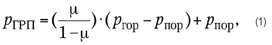
Where μ is Poisson ratio; Pгор (overburden), Pпор (pore) – overburden and pore pressures, respectively.
It was observed that in most cases the difference between the mud and cement solution’s hydrostatic pressure was equal or close to the pressure test value at the shoe of the previous casing and it also corresponds to the shoe test pressure which is always above or equal to the pressure which is required to enable the cementing of the casing in one stage. Thus, if pressure-testing of the rock at the casing shoe is performed successfully, it is possible to drill the well and perform interval borehole pressure testing at that pressure. During pressure testing it is possible to reach leak-off pressure for the newly penetrated horizon (sequence). If the static pressure of the drilling mud is above the rock stress, rock deformation will occur in the bottomhole area accompanied by fracture openings. Gradual pressure loading of the rocks is accompanied by pressure changes in these rocks with time, depending on the volume of drilling mud injected into the well.
The current method to determine the leak-off and fracture gradient consists of the following: drilling mud is pumped through a tubing string using the cementing units’ pumps either into the drill string with a closed annulus or into the annulus with a closed tubing string. Wellhead pressure is measured during injection at time intervals with minimum possible pump delivery. Concurrently with measuring pressure, the volume of drilling mud injected into the well is measured, and after the well opening up – volume of returned drilling mud. The data is used to build a wellhead pressure change curve versus the volume of injected drilling mud and/or injection period. When determining the leak-off pressure, injection of drilling mud is stopped as soon as the deviation from the linear relationship, between pressure and volume of injected drilling mud occurs. To estimate the rock frac pressure, the injection should be continued until rock fracking occurs [2]. A typical leak-off pressure change over time curve is shown in Fig. 1.
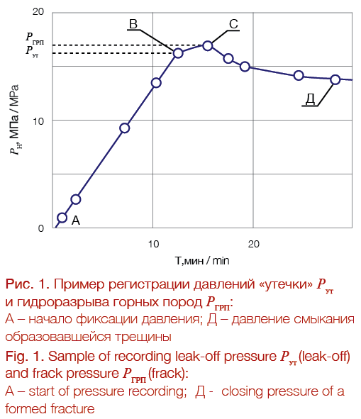
It can be seen from the Figure that the straight line reaches point B, starting from when the value and pressure curve deviates to the right. Starting from B, the pressure increase drops versus the same volume of injected drilling mud. Consequently, point B, where the transition from elastic to plastic deformation occurs, this is used to determine the leak-off pressure.
With further pressure increases upto point C, partial mud loss is observed due to opening of fractures and lost circulation. Point C corresponds to the pressure at which rock fracturing occurs – PГРП (frac). With further liquid injection at this point, pressure drops dramatically which testifies to the formation of fractures.
After the injection pressure at the wellhead at point B is recorded, leak-off pressure can be determined using the following formula:
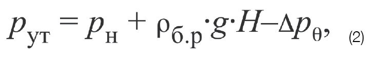
Where Pн (injection) – injection pressure at wellhead; ρб.р (drilling mud) – average mud weight in a well of H depth depending on average pressure and temperature e values; ΔPθ – drop in bottomhole hydrostatic pressure due to static shear stress θ when drilling mud is injected into a drilling string.
Planning Activity to Implement the Selected Solution
Based on the above it was planned to perform future operations using the following scheme:
1. Rock pressure testing at the shoe using the design or the leak-off pressure. This pressure is selected as reference pressure which together with the hydrostatic pressure will affect the cement and rocks at the shoe during oil, gas and water production and 100% replacement of drilling mud in the well by formation fluid [2].
2. Drilling out underlying rocks using drilling mud (lost circulation intervals) and interval borehole pressure testing at shoe testing pressure using the Leak-off test procedure. Thus, with increasing depth it is possible to obtain confirmed data. The procedure is performed during planned trip out of the bottomhole assembly at the column shoe. To take into account the effect of the drilling mud’s static shear stress on the pressure distribution in the borehole described above, the annulus and tubing pressures are measured.
3. When the target depth is reached, the actual well data becomes available which could be used to model the cementing. This enables the task of reaching the required cement top to be achieved and, with all the other conditions being equal, to commission a well which is fully in line with the design solutions.
4. The data received should be taken into account in accordance with the suggested geostatic model [3]. Group Well Design re-calculation should be also initiated using verified data and the updated information should be used in development with the new Group Well Designs.
Plan Implementation
For the first time, targeted borehole pressure testing was performed in Well No. 2 at the Konnovskoye Field. This field was selected for a reason (it is classified as a structurally complex field) and thorough preparation was performed before the work started. In the previous well No.1 at the same well pad, during drilling to run production casing, 13 lost circulation zones were penetrated.

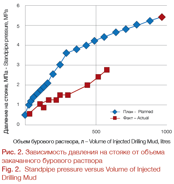
All the frac gradient values were taken into account when drilling Well No. 2 and the borehole was pressure-tested at 3162 m. The pressure-testing data and the pressure curve are shown in the Table and in Fig. 2. It should be noted that the pressure at which the leak starts, was not reached. This was done on purpose for a number of reasons, such as, that it was the first attempt, the value required to withstand the cement column pressure, etc.
This resulted in an unprecedented acceleration of well construction times in the Konnovskoye Field due to the careful consideration of all the technological solutions for the prevention of lost circulation. In the course of drilling only one lost circulation zone was penetrated at 3693 m. All the other zones were drilled without circulation loss and the zone at 3693m was eliminated with bullheading at the pressure determined during the pressure testing at 3162 m. Values of PГРП (frac) for this depth were taken into account and used to model the cementing process.
HSE requirements to the interval borehole pressure testing are no different from the requirements for pressure-testing of the well control equipment, and assessment of the technological risks, which comes down to the minimum permissible level when replicating the operations, thus testifying to the increased experience of our employed personnel.
Conclusion
Forecasting drilling mud losses through interval borehole pressure testing allows, in accordance with the actual field conditions and after being approved by a design institute, the selection of the required cement system and mud weight to ensure reaching the designed cement strength and top. Apart from this, it will provide information about the weakest area of the hole. Such information could be used to calculate a critical kick influx and prevent an underground blowout in case of gas, oil and water production. The received and updated geological information on the gradients will be used to plan future well construction and provide timely technological solutions to prevent mud loss.
The economic effect is attained due to saving on the drilling rig daily rates and on abandoning the use of cementing stage collars, as well as forecasting gas, oil and water production. Loss areas: considering that areas of mud loss are, as a rule, additionally penetrated through bullheading and the subsequent installation of a cement plug, the elimination of one such area of mud loss saves several million Roubles.
References
1. Staroshchuk A.V., Neftyanoe khozyaystvo = Oil Industry, 2011, no. 4,pp. 90-93
2. Semenyakin V.S., Semenyak M.V., Semenyakin P.V., Gazovaya promyshlennost’ = GAS Industry of Russia, 1997, no. 12, pp. 50–52.
3. Metodicheskoe rukovodstvo OLF-117 po tselostnosti skvazhin (Methodological guidance OLF-117 on the integrity of wells), Norwegian Oil and Gas Association, 2008.
This article is based on the presentation made by A. A. Voronin at the IX Multi-Regional Scientific and Technical Conference of Young Specialists (second prize). The article was published in the ROSNEFT Scientific and Technical Newsletter (Nauchno-technicheskiy Vestnik OAO “NK “Rosneft”) No.1, 2015, pp.28. Printed with permission from the Editorial Board.