REPSOL: ERD Drilling Experience in West Siberia, 2020 Operations
Introduction
This article looks the a case study of unique HMTL (Horizontal Multilateral) ERD project that Repsol as a part of a local Joint Venture has executed in Russia in 2020 within its Exploration and Appraisal campaign in the central part of West Siberia. The project included drilling of two complex shallow ERD Multilateral wells and their subsequent extended well tests.
HSE and QAQC Focus
Repsol places the utmost importance to HSE and quality. During the project, a Project Management Approach ensured a special focus was given to HSE and QA/QC during all operations and at every stage of the project.
On the HSE side – HAZID sessions were performed during operational planning (for logistics, mob/demob operations, drilling, testing) and during the execution phase, sufficient resources were allocated from operator’s side – two Field HSE engineers and one Regional Office HSE engineer, led by example in all operational safety practices.
On the QA/QC side of the business, a purposely designed campaign had been developed and executed with each service and material provider individually, enabling them to follow best practices and Repsol’s internal procedures.
ERD Classification & Trajectory
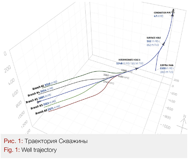
As per global industrial benchmarking, two wells that were drilled during the 2020 Campaign fall into the Shallow Extended Reach category with an average ERD ratio for main bore and all branches of 2.9.
Both wells have shallow kick-off, in surface section at ≈ 100m MDRT.
The well’s trajectories were designed to have pseudo-catenary profiles which assumes low initial build rates with a continuous increase of the dog leg severity, DLS (in steps) as the inclination angle increased. The maximum DLS figures were maintained as 3˚/30m above the ESP pump interval located close to the horizontal section and 9˚/30m within the target reservoir.
The benefit of the selected well paths assumed there was sufficient reduction in drilling torque as well as a casing wear mitigation. Both are of great importance, in the given case, it was important to considering the significant amount of string rotation hours during the massive directional work in the horizontal section of the well. Another advantage attained by minimizing the drag forces, the target depth provided more favorable conditions for a 4.5” liner installation.
The largest reservoir exposure amounted to 7657 meters of horizontal drilled length, which is a worldwide Repsol record.
Subsurface Overview & Geomechanics
In order to better understand the rationale behind the well design solutions such as the complex well trajectories and others, – it is important to give an overview of the local geology and subsurface environment.
The geological cross section itself is quite simple, consisting mostly of clays and claystone lithologies above producing horizons.
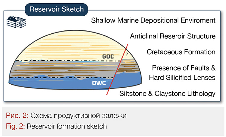
There are two geological targets (clastic reservoirs) ≈ 120m apart from each other in a vertical section. The thickness of both is quite small ~ 14 and 19 meters respectively. Both reservoirs are undersaturated with a gas cap above and an aquifer below.
The reservoir has a normal pressure regime, almost hydrostatic. Temperature gradient is 4.2 deg / 100 m. No sour gas presence (neither CO2, nor H2S – sweet environment).
The target reservoir is represented with a thin lamination of siltstones with claystones. The sketch below shows how the oil-bearing sand lenses are distributed within the clay stone massive (succession).
At this moment it should be clear, that the decision to drill such complex well trajectories is driven by the need to achieve the largest reservoir exposure. Fracking is not viable since the fracture propagation cannot be controlled in such a narrow oil window risking penetration of the water or gas cap. Acid treatments or any other stimulation techniques do not work either in the given reservoir lithology and minerology content.
In regards of geomechanics, the field is characterized by a normal fault stress regime where vertical stress is dominating and horizontal stresses are pretty much equal in all directions. (The field horizontal stresses anisotropy (~ 5%), so there is a minor difference wellbore-stability wise in the horizontal direction.
The existing claystone succession is very unstable and prone to breakouts in particular in highly deviated open hole intervals (related to the Intermediate Section). At the same time, due to the shallow depth environment, fluid loss and fracture gradients present relatively low values. All the above make the drilling window rather narrow.
Well Design Considerations
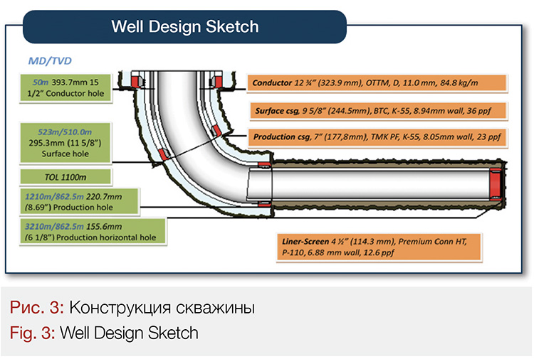
Continuing from the geological summary, there are no abnormal pressure intervals within the cross-section, lithology is rather uniform. Hence, it was central to drive the simplistic design that both wells have. Moreover, that common and unsophisticated 3-phase well design is field proven and has been optimized along the 10-wells exploration campaign that Repsol has undertaken in the field. The well design assumes conventional sizes: 12-3/4” conductor, 9-5/8” Surface, 7” Production casing, finishing with 4.5” liner-screen installed in horizontal reservoir section (only one main bore is cased with a liner screen at the last two multilateral ERD wells).
The uniqueness of the well design consists in the first ever approach to utilize ultra low viscous Water Base Mud (WBM) for drilling the most challenging and longest horizontal section. To mention that previous offset drilling experience was with Oil Base Muds (OBM) application.
That new concept proved to be feasible and rather effective. ECD was well managed within wellbore stability window, mud handling and cuttings treatment ended up being easier, safer and more environmentally friendly, and at last having positive compatibility with the reservoir. The greatest advantage was achieved at cost side, for WBM solution being considerably cheaper, as the main mud treatment process – continuous dilution was enabled just by drill water against expensive base oil in OBM.
To justify the concept and confirm assumptions of the water base system application several tests were performed during the planning phase:
• Inhibition test with samples of the core: Monovalent brines NaCL, KCL, NaOH (pH=9) sufficiently inhibits the core samples.
• CEC test – to measure drilled solids reactivity. Resulting in evidences that indeed drilled formations could be considered low reactive (performed on existing core sample).
• PST Test – performed to ensure that the production screen will not get plugged
Good hole cleaning was granted by the Turbulent Flow regime that was possible to achieve due to thin mud rheology and ensured by the best operational practices for ERD wells.
The completion design strategy of the five horizontal lateral bores considered casing only the main bore with a 4.5” liner and leaving the laterals open. That decision to leave lateral boreholes non-cased was to assess and monitor the incremental production and understand how long the open hole laterals would sustain production flow rates and when the boreholes would collapse. Extensive geomechanics studies were performed in this regard with the key output being the drawdown strategy developed that allowed smooth stresses redistribution with the appearance of so-called “Arch Effect” during the well flow period.
The liner string itself was designed as a combination of screens and blank joints, that are distributed across the intervals with better and worse reservoir properties respectively.

The lower completion string had a double contingency to plan against any risks of a failed run and installation which was estimated by the torque and drag modelling. T&D simulation models presented a risk of Liner Installation and Reaching TD with WBM in case of poor hole condition and high FF (FF>0.35, which could be very possible). Therefore, doubled contingency was planned in a form of:
• Downhole swivel, that would allow to remove axial drag of the landing string in cased hole, by applying rotation of the same landing string. The option was
taken into account and planned for as the length of landing string is quite significant, so the idea was to estimate such effect.
• High Torque connections, which in a worst case could let us rotate the whole running string
Another reason for a double contingency was the lack of knowledge of how the WBM would perform, as well as the need to test options for a full field development case.
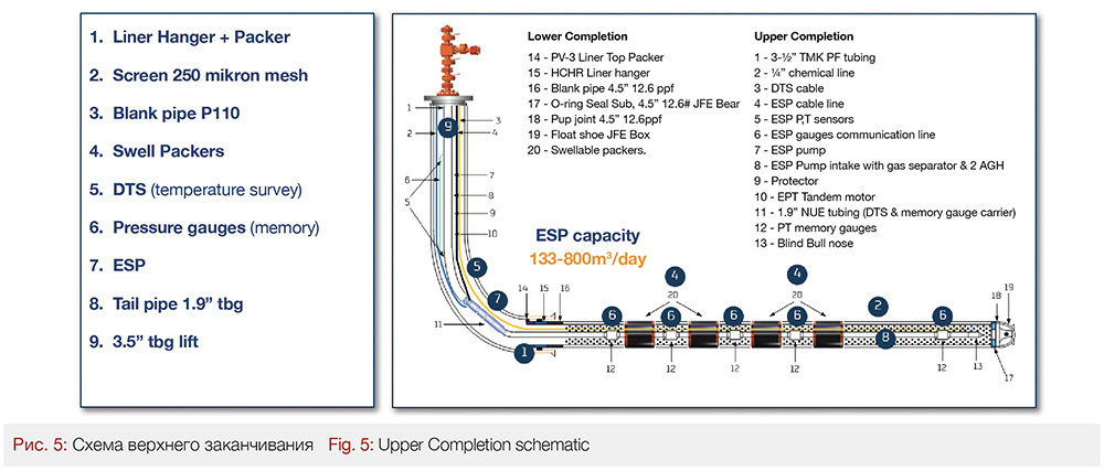
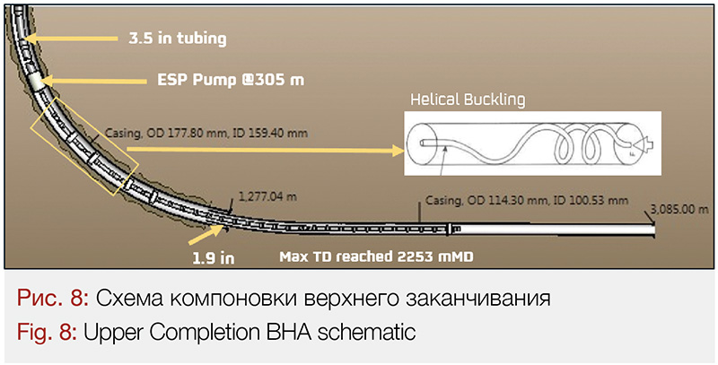
In regards of the upper completion, it was designed to allow for an extended well test and included the ESP as artificial lift option, DTS (Distributed Temperature Sensing with optic fiber) was placed along the horizontal reservoir to control inflow contribution from different intervals (real time) as well as memory pressure gauges (not Real-Time), all conveyed downhole to TD via 1.9” Tail pipe (tubing) inside 4.5” Liner. Swellable packers (oil-water reactive) were placed from each side of the sidetracking windows to provide opportunity for selective laterals isolation should any water or gas breakthrough occur. The upper completion assembly was to be run on a 3.5” tubing (inside 7” Production casing).
ERD Challenges
The drilling hydraulics were critical and in focus during both planning and execution phases. ECD management was regarded as a main challenge for these ERD wells based on the nature of well design (shallow TVD and extended laterals) and offset experience.
Based on the preliminary modelling it was obvious that the high potential of exceeding the minimum horizontal stress with a risk of mud losses existed.
To be able to manage the equivalent circulating density (ECD) in a most effective way, as was mentioned above the ultra-low viscosity drilling fluid was utilized for the first time at the project. The wellbore stability was also a potential issue as per the geomechanical model where pulling the string dry led to the breaching of the low and medium collapse gradients due to the swab effect.
Following best ERD industry practices, the drilling fluid rheology (low-end R6/R3) in long horizontal slim holes (which our case is considered to be) is a key ECD driver. The ECD management strategy was mainly focused on the precise control of the mud rheology parameters.
The ultra-Low viscosity fluid had very low low-end rheology numbers itself (1 and 2 Fann Viscosimeter Dial Readings at 3 and 6 rpm respectively), which was the main idea to utilize this type of mud. However, it should be noted that even with a slight increase in downhole rheology caused by dissolved fine solids, especially when drilling across the claystone, resulted in a significant ECD increase. Unlike the described process, the rest of the factors as ROP or Off-bottom clean-up time had much less impact on ECD. This is just to confirm that downhole rheology is the greatest ECD impacting factor from all.
ECD management practices for the 155.6 mm (6 1/8”) hole section required constant dilution at a slow rate and periodical dumping of some fluid volume from the flow line directly to the waste pit, while simultaneously introducing fresh fluid to the active tank when the MW / rheology out was observed to be increasing. This was done while drilling all 5 horizontal branches on each of two wells and enabled drilling as fast as 37 – 40 m/hr avg ROPi (instantaneous) with the short term increase up to 60 m/hr by the end of Main Bore with no reaming / additional clean-up cycles or wiper trips. Finally, a lot of the well construction time was saved by avoiding these unnecessary operations.
Continuous dilution was essential also because the solids control equipment did not manage to screen out such fine and well-grinded drilled particles. That was partially attributed to the lithology content and the process cuttings undergo on the way up the annulus, being crushed by continuous and long-lasting drill string rotation at 100-120 RPM.
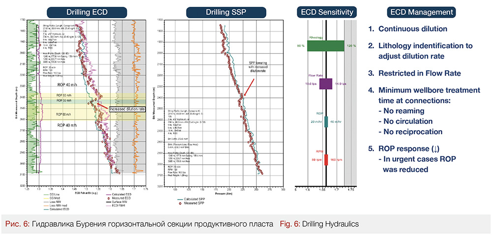
The implementation of the mentioned ultra-low vis fluid was really a novel approach in this case. The concern here could be related to the sufficiency of mud carrying capacity, however, the ultra-Low viscosity fluid proved to be effective for both ECD management and for hole cleaning purposes. Landmark WellPlan hydraulic modelling was calculating the flow regime as turbulent, whereas the ERA software modelling was showing the flow regime in the annulus as not fully turbulent but being in transition zone from laminar to turbulent. Nevertheless, the actual hole cleaning process wasn’t significantly affected as confirmed by the hook load roadmaps.
The only potential issue with that specific fluid was fast sagging of weighting material (CaCO3) in case some unplanned activities took place not allowing to circulate for a long time. Therefore, in order to avoid compromising hole stability, all intermediate trips from Branches TD to KOP have been conducted with circulation to compensate for the swab effect – in backreaming or pump out modes.
Another Horizontal Section Drilling Challenge was the multilateral trajectory profile itself, which required as low as a DLS as possible for sidetracking from every branch to the main hole and high DLS while deviating from the main hole to the branches. The directional drilling contractor demonstrated excellent performance in both the well path execution and directional tools operational performance far beyond the standard hours (450 hrs performed vs. 250 hrs guaranteed) – owing to the QAQC activities performed in advance.
On top of the described drilling issues there was one design-related challenge that required significant cased hole friction factor limitation for the upper completion string installation to avoid any string lockup (will be covered further).
ERD Practices
As only the main bore was planned to be cased with a 4-1/2” (114.3 mm) liner, with all the branch holes left open, there was no need to clean the Branch holes from residual cuttings during the trip out to the KOP. In addition, the aim was to minimize the residual cuttings transfer from the branch to main hole to avoid any potential problems on the final trip out from the main bore TD. In light of this, the decision was made to pull the string out from the branch holes in pump out mode (full flow and no rotation) and perform the backreaming on final trip out from the main bore. Tripping out from the 1st branch went relatively smooth but starting from the 2nd branch some excessive drag and deviation from the expected trends were observed, indicating the potential packoff condition. No cavings were seen from the HZ interval during both drilling and backreaming. Hook load trends had good correlation with ECD fluctuations.
Finally, the trip out strategy was modified and the backreaming from branch holes was enabled instead of pump out. Cleaning out the hole while backreaming instead of “bulldozing” the cuttings while in pump out made the operations considerably safer. The negative impact of backreaming out of the branch holes was the increase in the frictional factors in the main bore while further drilling due to the residual cuttings transport from each branch to the main bore above the KOP. The Main Bore PU/SOFF were increasing in average by 0.05 after the backreaming from each Branch. However, this didn’t result in any problems during the final backreaming out of the main bore.
Upper Completion Issue
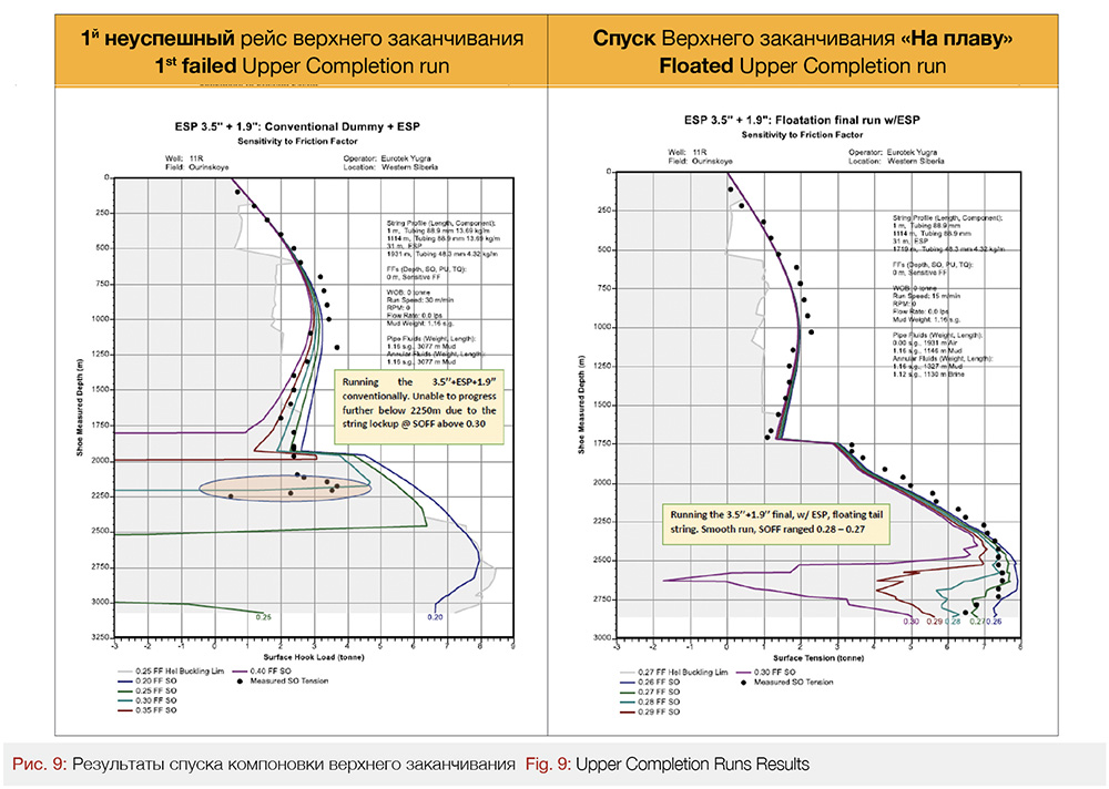
The unexpected problem happened with upper completion string installation. The string design (3.5’’ TBG inside the 7’’ casing and 1.9’’ TBG inside the 4.5’’ liner with the ESP in between) had a limitation of the max cased hole SOFF of 0.20 to get the string to TD. The preliminary Wellplan (Landmark) T&D simulations did not show any issues with upper completion installation. However, once a detailed BHA was introduced into the model, the results of K&M’s ERA software showed that any SOFF numbers higher than 0.20 would result in string lockup. During execution, the first unsuccessful upper completion run showed an actual CH SOFF of 0.30 and the weight went to zero (string lockup) exactly at the depth predicted by ERA software for SOFF of 0.30. The lockup point was in the 1.9’’ TBG below the ESP at a distance where the lightweight tubular with less buckling resistances were still inside the 7’’ casing with the more room to get buckled at same compression in comparison with 1.9’’ tubular inside the 4.5’’ liner.
As a solution to this issue it was decided to go with a flotation option and run the upper completion string with the “mud over air” scenario having 1.9’’ TBG filled with air and isolated with blank collars. That undertaking significantly reduced axial drag and, as the result, mitigated compression in transition zone between 3.5’’ and 1.9’’ tubular, getting more room in terms of SOFF. The ERA software simulations showed substantial potential improvement – the floatation scenario shifted the “no-go” limitation of SOFF from 0.20+ to 0.29+. The dummy run that was performed thereafter with no ESP / mandrels / cables proved the flotation concept to be successful with the SOFF ranged 0.30 – 0.28 with the downtrend to 0.26 towards TD. The final upper completion run showed same positive result with no helical buckling / lockup related problems. The drag reduction in 1.9’’ TBG was achieved by reducing side forces of empty tubular and as a result the compression in a weak zone below the ESP was also reduced below the lockup critical value.
Operational Results Summary
The man objective of the project – to prove the feasibility of drilling these extended reach horizontal multilateral wells, was successfully fulfilled. Both wells have been accomplished under budgeted time and cost, gathering valuable technical input for preparation of the full field development case.
Positive Highlights
1. Sidetracking operations. Was regarded as a risky operation, since it has never been experienced before at the project. All sidetracking operations were executed smoothly with continuous time optimization (from 8 down to 1.8 hrs).
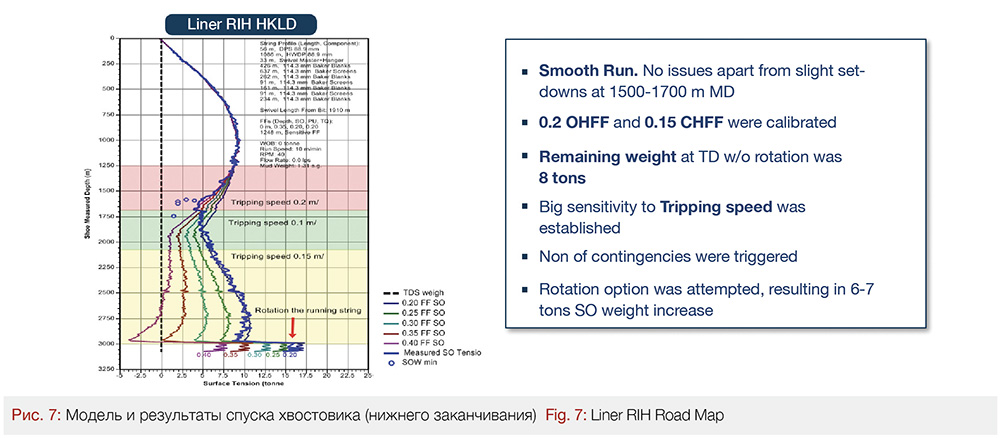
2. Liner Smooth Run was a successful achievement, first – by landing it in the correct (main) borehole and second – not having any drag related issues, friction factor calibrated as minimal as 0.2 OHFF and 0.15 CHFF. A large sensitivity to the tripping speed was established. None of the contingencies had to be triggered (Downhole swivel or full string rotation).
3. Downhole tool performance was outstanding, most of the tools operated beyond their regular guaranteed working limits. DD contractor was proactively involved in QA/QC process, meeting all the Operator’s standards and process requirements. That saved much of the well construction time by avoiding trips to surface.
4. Drilling fluid performance. Special in-house designed ultra-low viscosity drill-in fluid was a decisive factor in the project’s success. The concept became field proven being fit for shallow ERD applications, in this particular reservoir formation and, at the same time, providing economic benefits in terms of reduced costs and increased environmental friendliness comparing to the previously used fluid on the project, OBM.
5. Performance optimization. Two-well drilling campaign was a good foundation to be able to optimize drilling practices and seek new efficiencies. The 40-minute Weight to Weight connection time was decreased to 14 min WtW time per connection, just focusing on the wellbore conditioning, surveying, measurement and connection practices.
Areas for Improvement
1. Rig equipment failures. The negative side of the standalone projects such as this one is the scarce rig availability. The experience with a new manufactured rig came with numerous breakdowns of different rig equipment that eventually led to a significant downtime.
2. Upper Completion installation the issue was driven by lack of detailed planning from both the operator and contractor’s sides. Specific dimensions of the BHA elements appeared to be very impactful to the operations feasibility. An important lesson was learned with the tail pipe of the Upper Completion BHA flotation. One more lesson to learn was the advantage gained by having the appropriate and adequate historical technical data from similar operations to enable the opportunity to perform more accurate and reliable engineering modelling in any software (WellPlan or ERA).
3. Data transmission rate limitation became a limiting factor in the horizontal reservoir section drilling performance optimization, restricting instantaneous ROP. The solution to that is to implement a new generation downhole pulsers (e.g. Baker Hughes BCPM 2) with increased data transmission capacity.
Authors
Erik Abalian, Artur Abalian, Andrea Martin Atanes
REPSOL

