Tatneft: Reducing Logistic, Diagnostic and Maintenance Costs of Downhole Pumps and Tubing

In Tatneft today, “business challenges” occupy a considerable share of the company’s set strategic goals. These are strategic and technical tasks which are set to deliver fold increases in production asset efficiency. About 30 such “challenges” have been identified in different areas, which include searching for technologies that enable the development of hard-to-recover assets, technologies aimed at extending the economic life of depleted fields and using cost effective technologies that have a low implementation risk. The primary evaluation of these business challenges has shown that it is impossible to solve them without using innovative solutions.
It is usually impossible to solve the entire problem at once, therefore, a business challenge is, as a rule, broken down into separate constituents – technical challenges. The latest technical challenges, identified as part of the asset analysis in the Center for Technology Development in Tatneft, kick started our innovation projects. Such project stages include; searching (development), practical evaluation and replication of the technologies that have been missing in the Company’s technology portfolio.
The previous most significant technology challenges included: reducing high OPEX for logistics, diagnostics and maintenance of downhole pumping equipment (DPE) as well as other considerable oil production expenditures.
In an oil well’s operational life the tubing is subjected to various external and internal pressures and forces which result in the degradation of metals, mechanical damage, corrosion, cracks appearing and developing on the surfaces of the pipes, as well as the formation of other various defects. It is very important to detect such defects in a timely manner prior to the tubing’s failure. Various methods of non-destructive testing have been used for this, the most widely used is tubing electromagnetic integrity defectoscope inspection.
Almost half of Tatneft’s entire expenditures for the repair and maintenance of DPE is spent on tubing. Such considerable expenditure is explained by the fact that the transportation, diagnostics and repair is mostly carried out on the entire tubing string since it is impossible to determine the equipment fault point locally, and the DPE is shipped to the workshops for repair.
A classic solution for tubing diagnostics and repair work is to run the total cycle of the pre-washing line (cleaning the tubing of well fluids after the tubing is removed from a well) and the high pressure washing line (cleaning of the internal surface of the tubing from scale and residue), tubing collar back-off tool, wiper trip unit (calibration pigging for tubing), the defectoscope line (tubing wall thickness and defect control), pipe-threading machine, tubing collar back-off line, hydro-testing and the labeling of the tubing (Fig.1).

The most obvious way to optimize transportation, diagnostics and tubing repair is to move the service centre to the wellhead. The task of researching and testing a mobile wellhead diagnostic complex was solved as a result of the joint efforts by the specialists of the Center for Technology Development and Tatneft’s “Elkhovneft” Field Office.
Several solutions were considered to adapt the existing logging tools, including the following technologies:
• downhole flow and temperature measurements;
• acoustic noise logging;
• tubing NDT during removal from a well.
Downhole flow measurements have already been used by oil companies for a long time and they do not require any attention. The main disadvantage of this method, in the context of this problem, is the impossibility to detect tubing defects that have not yet become fully opened perforations.
Another solution is to use acoustic noise logging. In 2017 and 2018, some experimental trials were carried out by the specialists of the Center for Technology Development and the “Elkhovneft” Field Office to localize the downhole equipment failure areas using downhole diagnostics consisting of a defectoscope and an acoustic noise logging device. The principle operation of a defectoscope is to measure the decreasing intensity of magnetism in a metal after it was subjected to an impulse magnetic field, while the principle of operation of the downhole noise logging device is based on recording the acoustic noise produced by fluids passing through perforations in the tubing string.
While running field tests on the downhole diagnostic system, 7 x 73mm diameter tubing strings were prepared with various artificial flaws – perforations, defects on the external surface and thinning of the tubing wall thickness. The test results confirmed the technological operation of the inline noise logging and identifying the tubing perforated defects. The accurate identification of the tubing defects using smart pigs was not successful in the trial.
Following on, based on the studies of the best professional foreign practices conducted by the teams, the testing of the mobile non-destructive testing service centre was scheduled. The service centre automates the non-destructive testing of the tubing using electromagnetic inspection.
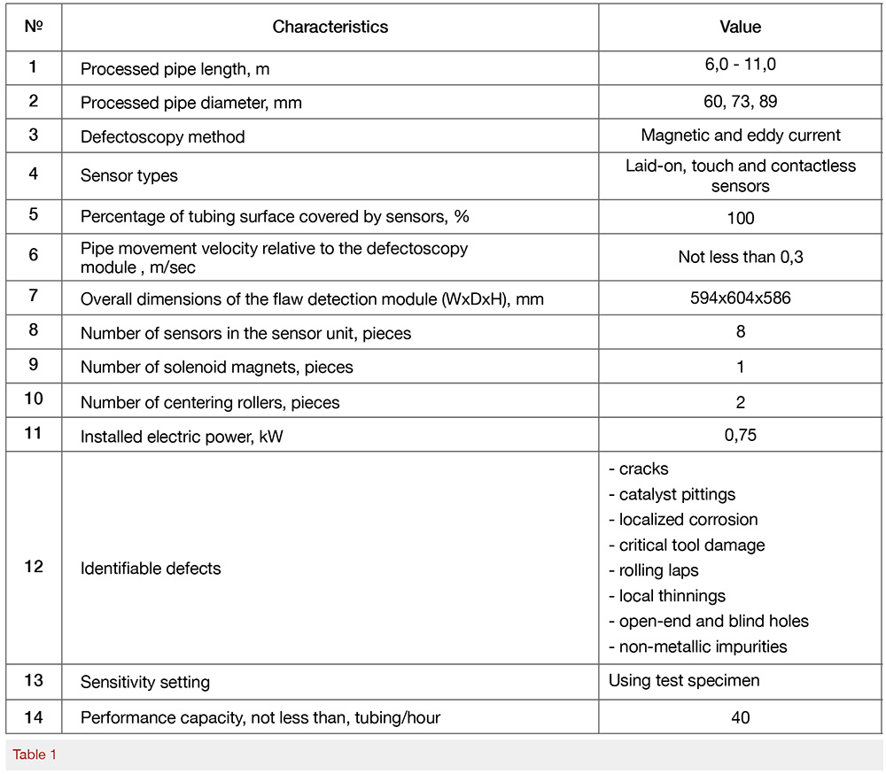
Defectoscopy was conducted during POOH operations and was conducted by the inspection servicing and well workover crews, directly at the wellhead. Moreover, the method makes it possible to detect defects on the external and internal surfaces of the tubing. The basic technological characteristics of the system are presented in Table 1.
The diagnostic module is mounted on a spider (it is designed for seizing and hang off the tubing string) so that the tubing string could pass through it (see Fig.2), this is connected to the hardware and software systems of the unit using a cable. The non-destructive testing is conducted simultaneously while the pipes are being recovered from the well, the information regarding the current status of the pipes is presented by an optical signal, and it is also possible to scan and archive the primary control data onto a computer hard drive. To control the different diameter tubing, it is necessary to replace the sensor unit for the relevant type and sizes of the pipes. After the diagnostic module is assembled, it becomes necessary to lift the wellhead working platform, the hydraulic tongues and the working platform of the current well servicing the operator. Prior to operations in case it is necessary to replace the sensor unit, it is necessary to test the sensitivity setting of the sensors, using a test specimen of tubing. The time required for assembling, disassembling the diagnostic system and testing the sensitivity of settings of the sensors, is around an average of 40 minutes per one repair job.

To run the field trials, wells were selected which had been waiting servicing and had leaking downhole pumping equipment. The Company’s 8 producing wells, having had a mean time before failures of 552 days, became the testing targets. The field trials were implemented in two stages: the first stage included inspecting the pipes at the well site, while the second stage was carried out in the service workshops.
Over the course of the field trials usability, correct operation of the defectoscopy module and changes in the duration of well servicing were all assessed.
As the tubing was recovered from a well it underwent defectoscopy inspection with the results displayed in real-time on the computer (see Fig.3) alongside the evaluation signal (red – for defected tubing; green- for useable pipes) with an acoustic signal.

Based on the results of the tubing defectoscopy, the tubes were sorted into the reusable and rejected.
After the rejected tubing pipes were backed off and laid down on the catwalk they were labeled for examination.
After recovery, the disassembled tubing strings were delivered to the service workshops for DPE repair, running the full cycle of repair and diagnostics, and also to analyze the data obtained during POOH operations using the equipment in the pipe repair shops.
In total, 1173 tubing pipes have been processed for DPE repair and maintenance over the course of the trial, at the repair workshops and at the wellhead. Notably, 229 tubing pipes were rejected via defectoscopy during well servicing, while 231 pipes were rejected at the stationary diagnostic stand, of those 224 had been rejected over the course of POOH operations (see Table 2).

Thus, the total difference between the results was about 2 per cent; that notwithstanding, by running the tubing defectoscopy at the wellhead it in no way affected the time to recover the equipment from the well. It was determined that the presence of asphaltine precipitation on the recovered equipment did not have any effect on the quality of the defectoscopy.
In general, taking into account the results obtained over the course of the trial, it is possible to state that the mobile system confirmed its efficiency, proving the accuracy of the diagnostics was comparable to any of the stationary systems installed at the service workshops. The data obtained over the course of the test confirmed that the volume of tubing delivery and repair was optimized by 80 per cent.
Despite the positive results during the trial, a number of features of the mobile system required modification. First, it is necessary to deliver the potential of performing defectoscopy testing at the well site with an ESP (due to the presence of cables); it is necessary to minimize the overall dimensions of the diagnostic module and it is necessary to enable its installation using truck mounted workover rigs.
The recommendations were sent to the manufacturer of this equipment for its retrofit.
The economic effect of the introduction of the mobile wellhead system of non-destructive testing of tubing is based on the OPEX savings that have reduced transportation, repair and diagnostics of tubing costs due to the fact that only actually rejected tubing pipes had to be replaced and delivered to the DPE repair workshops.
Authors

Ilnur Valeev
Head of the Project, Project office of the Technological Development Center, Tatneft

Lenar Karimov
Lead Expert, Division of Expert & Methodological Support of the Environmental Protection & Ecology Department, Tatneft

Marat Timerzyanov
Deputy Head of the Oil Production Engineering & Technology Division of the Oil & Gas Production Directorate of the Oil & Gas Production Department of JV Tatneft-Dobycha, Tatneft