Technical Regulations for Measuring Instrumentation for Logging Operations

Introduction
Well construction is a complicated process from an engineering point of view involving a number of tasks relating to a wide range of technologies.
In the most cases, each task is performed using a separate tool not related to the others. So a lot of data is used inefficiently or not used at all. We offer a concept of a comprehensive approach to the whole well construction cycle from designing to field development and production. It is aimed at optimizing the well construction process, to provide control of the geological and technical drilling parameters, MWD support of drilling operations based on adjusted 1D MWD models, correction of mud window and other parameters to minimize formation damage and to prevent emergency situations, forecasting and prevention of emergency situations, geosteering and optimization of the reservoir entry based on the original proprietary technologies.
Fig. 1 shows the concept diagram.
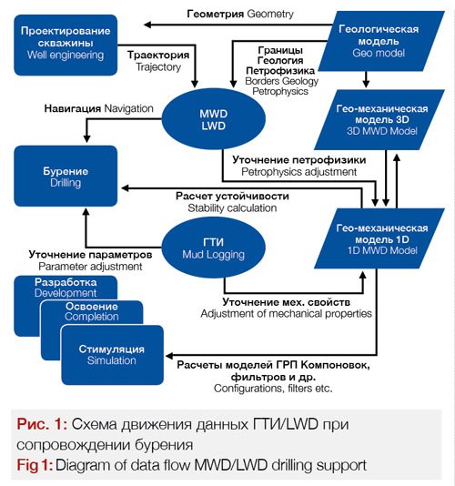
The details of creating a 1D geological MWD model including open wellbore stability calculations are contained in our earlier works [1-2]. Drilling support including the application of comprehensive surveys (MWD and LWD) is demonstrated with the example of a well in Eastern Siberia in our work [3]. Methodical foundations of MWD petrophysical interpretation were established by E.E. Lukyanov [4-7] and successfully used by NovosibirskNIPIneft LTD in experimental and methodological works involving actual data.
From a petrophysical point of view, MWD and LWD data during drilling have an advantage over well logging data because they provide recording of physical characteristics either directly at the moment of tool interaction with the geologic environment (MWD) or after a minimal period of time (LWD) after penetration, when physical characteristics are not yet changed as a result of introducing muds.
In this work, we will focus on technical regulations for performing surveys providing input data for creation of reliable geological MWD models for drilling support.
Technical regulations for MWD
During well construction, there are multiple factors capable to hinder or accelerate well construction process. Negative factors hindering construction include low quality of initial and processed data from surface sensors of MWD tools and bottomhole telemetry sensors, insufficient professional skills of the staff, accidental external non-system factors, which cause an increase in the number of emergency situations and construction delays. Positive factors accelerating construction include, besides high quality of initial and processed data and well-trained staff, the introduction of new design parameters obtained through processing of both existing parameters and absolutely new parameters resulting from development of new instrument types.
Most manufacturers to different extents consider the requirements of RD 153-39.0-069-01 [8] and GOST Р 53375-2009 [9] when developing and designing their equipment, some issues shall be noted which were not described in the regulatory documents because some modern electronic and engineering technologies did not exist at the moment of the document acceptance. Performing measurements with the up-to-date equipment allows accuracy to increase up to two decimal places within the range 0–100 and decrease the measurement error down to the four decimal places within the measurable range. The final error and accuracy of a sensor will depend only on the sensor design because the electronic and measuring parts will have neglectable influence to the measurements. The metrological problems of MWD sensors were considered in the works [6, 17-19].
Currently, the low quality of initial data from the surface MWD sensors is due to the following reasons:
design;
• obsolete components;
• low accuracy and high measurement error;
• low quality of communication lines;
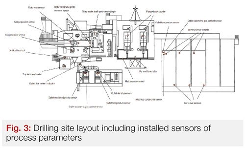
• incorrect sensor installation at drilling site;
• violation of regulations and schedules for verification.
Elimination of the above mentioned factors will significantly increase the quality of the initial data. Therefore, we can offer the following model of an ideal sensor.
The sensor shall include the following components: primary transducer to transform physical impacts into electrical signal; amplification and conversion unit to convert the electric signal into code (various types of amplifiers and ADCs); driver data bus, real-time clock, back-up power source and microprocessor unit for primary code conversion and signal normalization using some algorithms, data exchange through external network, storage of calibrations, normalization curves, and other metrological meta-data. Besides of that, the following requirements are applied to the sensors and lower-level data acquisition system.
1. Parameter transmission using actual units.
2. The sensors shall have temperature compensation units and contain algorithms considering temperature influence to initial measurements.
3. Data buffering in case of short-term communication failure.
4. Back-up power supply in case of failure of the main power supply. To provide power saving, only measurements and internal data storing are allowed. Other hardware shall be shut down.
5. Synchronization of internal real-time clock using external synchronization signal received via data field bus.
6. Internal self-diagnostics system with logging sensor failures.
All sensors and systems shall use a common network.
Implementation of the above requirements became possible as a result of the development of electronic components with low and ultra-low power consumption. Due to the creation of a wide range of a new type analog-to digital converters with integral sigma-delta filter, the resolution of sensors processing analog signals can be increased up to 16 digits without any measurement error increase. Sensor installation places for each drill site shall be justified and agreed with the customer and drilling contractor with the signing of a relevant document.
Below there is the list of the sensors updated in accordance with the above mentioned requirements.
1. Small-size high-precision wireline load sensor
It has a digital interface, factory-calibrated. The sensor tolerates to clamping screw tension.
Characteristics:
• load measurement range: 0…20 tons;
• load limit: 25 tons;
• limit of admissible intrinsic reduced measurement error: 10% (with 0–1 ton), 3% (with 1–20 tons);
• cable diameter: 24…35 mm;
• operating temperature range -40…+50 ˚с;
• instrument weight: 4 kg.
RPM sensor
The sensor is designer to convert the drill winch rotation angle to pulses directly proportional to the hoisting block travel. The sensor has a high resolution comprising 180 pulses per rotation, which, depending on drum diameter, allows for the measurement of the hoisting block position with an accuracy of 5–20 mm. The sensor has an independent memory and power supply that allow to protect linear calibration table from power supply failures.
Characteristics:
• pulses per rotation: 180;
• maximal allowable rotation speed: 10 rpm;
• absolute measurement error: 1.0;
• instrument weight: 5 kg.
Combined mud density, level and temperature sensor.
Combined sensors allow to resolve several well logging tasks during drilling. High-precision high speed measurements of level, density and temperature allow real-time monitoring and correction of drilling process to provide optimal mud selection. The small size of the sensors allows installation inside vibration screens to allow high-precision mud measurements at the well outlet to determine productive horizons and gas showings.
Characteristics of measured parameters:
• density: measurement range 800…2200 kg/m3; relative error ±0.1%; resolution 0.1 kg/m3;
• level: measurement range 0.5…3.0 m; relative error ±0.1%; resolution 0.001 m;
• temperature: measurement range 0…+80 ˚C; relative error ±0.25%; resolution 0.01 ˚C
Specifics:
• determining values of three parameters using a single instrument;
• high-precision density, level, and temperature measurement;
• low time constant;
• inlet/outlet sensor installation.
Sensor tests at the drilling site, show loss of initial data due to accidental or intentional communication line and power supply cable failures became almost impossible, which had positive consequences for all the data as a whole.
At the same time, it shall be considered that, though this modernization improves work quality during construction, it does not bring the work quality to a new level. For higher quality, we shall introduce new types of sensors which are currently not present in the standard set of MWD sensors. Modular nature of MWD allows to satisfy practically all metrological needs [11] with limitations, which are mainly due to
the sensor costs.
In modern MWD stations, as a rule, there is no mud flow meters at the annular space, and the stations are equipped with flow indicators without mass flow metering feature. This is primarily due to high cost of the sensors and their large size and weight, which does not allow their mounting at the drilling site. These measurements can be performed with the use of immersion solenoid flow meters. They are very precise, small, and inexpensive.
Characteristics:
• measurement range: 20…800 m3/h;
• intrinsic reduced error: 2.5 %.
Environment parameters:
• specific electric conductance: 10-3 …10 S/m;
• temperature: 0…150 ºС.
Specifics:
• installation without changing drilling site chute system;
• easy mounting and unmounting;
• chute size from 100 to 1000 mm;
• high accuracy;
• low cost.
Volumetric gas content sensor for mud (Lukyanov E.E., Lukyanov K.E., Kayurov K.N., Eremin V.N., A system for automatic measurement invention patent RUS 2310069, 20.11.2007)
Unique development of SPEGE Looch allowing to determine with high precision volumetric gas content in drilling mud. The sensor performs discrete measurements of volumetric gas content, density, temperature, and electric conductance of drilling mud and calculates Joule-Thomson coefficient with 30–60 s intervals. The use of the device allows real-time detection of productive horizons and provides safety control during penetration; when installed at the inlet, it provides calculation of actual equivalent mud density on the hole bottom.
Characteristics of measured parameters:
• volumetric gas content: measurement range 0…40%; relative error 0.5%;
• density: measurement range 700…2200 kg/m3; relative error 1%;
• specific electric conductance: measurement range 0,02…20 Ohm/m; relative error 0.1%;
• temperature: measurement range 0…80 ºС; relative error 0.1%.
Specifics:
• high-precision measurements at inlet and outlet;
• ensuring safety and increasing quality of reservoir penetration;
• obtaining unique parameters;
• determining area with high gas saturation;
• calculation of actual bottomhole mud density;
• quantitative gas logging.
Therefore, the introduction of new software and hardware technologies and development of new surface sensors reduces the emergency level and increases technical and economic performance indicators of well construction.
In addition to the above mentioned sensors, a system is being developed to provide automatic measurement of volumetric gas content and vortex degassing of drilling mud including well inlet and outlet subsystems (inventor’s certificate will be issued).
As a result of the use of the system for automatic measurement of volumetric gas content and vortex degassing of drilling mud, proposed as an invention, we can obtain in real time the following parameters having their own value for the process:
• mud temperature before and after heating;
• volumetric gas content in the mud;
• true density of the mud;
• electrical conductivity (specific electrical resistance) of drilling mud;
• drilling mud degassing including determining of degassing coefficient;
• analysis of produced air-and-gas mixture (AGM) including determining of O2, CO2, H2, H2S, CH4, C2+ levels;
Ⅸ AGM transfer for chromatography and mass spectrometry.
The proposed system is distinguished from other devices of this type by a number of features, including:
• increased reliability of outburst hazard forecasting;
• comprehensive approach to resolving of set tasks, allowing to change gas logging status from a qualitative to a quantitative method, moreover, it obtains petrophysical foundations;
• continuous process of receiving information, both on volumetric gas content and drilling mud degassing, which significantly increases resolving capacity of gas logging method;
• possibility to receive information basis for continuous gas-and-sludge monitoring during gas circulation in parallel with performance of gas logging tasks;
• significant increase of the system operation reliability through a number of declared features missing in equivalent systems.
Power logging parameters provide foundation for real-time receiving of MWD parameters with the well deepening, i. e. directly from under the drilling bit and can be determined using an alternative technology tested on a number of wells [18]. Recommended operation sequence for MWD parameters calculation using the parameters obtained during drilling will be described in [18].
Technical Regulations for LWD
Use of logging while drilling requires new approaches to improve metrological characteristics and reliability of all bottomhole telemetry and geophysical equipment, due to specifics of operations in heavy-duty conditions [13]. The main negative factors include high vibration level, high temperature and pressure, which can result in early failure of telemetry systems. Large-scale production of modern electronic components with a automatic temperature ranges reduces the amount of failures and to improve metrological performance [14]. Technical regulations for logging while drilling are similar to those for regular logging and are described in detail in RD 153-39.0-109-01 [14].
Below is the typical scope of the equipment:
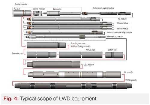
Metrological requirements for the telemetry systems and LWD modules shall conform to the requirements of RD 153-39.0-072-01 [15].
Requirements for inclinometers for surveying uncased wells:
• azimuth measurement range: 0 to 360°;
• measurement range limits for zenith angle: 0 to 45, 90, 135, 180°;
• measurement range for apsidal angle: 0 to 360°;
• admissible intrinsic error of azimuth measurement for zenith angles exceeding 3° – within ± 2°;
• admissible intrinsic error of zenith angle measurement Ⅸ within ± 0.5°;
• complementary error caused by supply voltage change Ⅸ not exceeding 0.2 of intrinsic error;
• complementary error caused by environment temperature change shall not exceed 0.1 of intrinsic error per 10 °C relative to standard temperature value comprising 20 °C.
Requirements for gas logging modules:
• standardized metrological characteristics include exposure dose rate (EDR) or equivalent weight content of uranium, which are calculated based on measured pulse counting rate;
• EDR determining range: 0 to 250 µR/h, equivalent
weight content of uranium: 0 to 200 ppmU;
• limits of admissible intrinsic relative errors of EDR determining: ±15 %; equivalent weight content of uranium: – ±[4.3 + 0,7(200/Ue – 1)] %, where Ue is equivalent weight content of uranium, ppmU;
• admissible complementary error of determining caused by supply voltage change within ±10 % shall not exceed 0.2 of intrinsic error;
• admissible complementary determining error due to temperature change in the well shall not exceed 0.1 of intrinsic error per 10 °C relative to standard value comprising 20 °C.
Requirements for gamma-gamma density logging modules:
• standardized metrological characteristics include rock volumetric density and photoelectric absorption index, which are calculated based on measured pulse counting rate;
• volumetric density determining range: 1.7 to 3.0 g/cm3;
• photoelectric absorption index determining range: 1.3 to 7.0;
• limit of admissible intrinsic relative errors of density measurement within 1.7 to 2.0 g/cm3 and 2.0 to 3.0 g/cm3 shall not exceed ±1,5 % and ±1,2 % respectively;
• limit of admissible intrinsic relative errors of photoelectric absorption index measurement shall not exceed ±0.2 (in Ре units);
• admissible complementary errors due to supply voltage change by ±10 % and temperature change in the well by 10 °C relative to the standard value comprising 20 °C shall not exceed 0.2 and 0.1 of intrinsic error respectively.
Requirements for lateral logging (LL) modules:
• specific electric resistance measurement range: 0.2 to 10000 Ohm · m;
• the limit of admissible intrinsic error of specific electric resistance measurement: not exceeding ± 5%;
• admissible complementary error of specific electric resistance measurement caused by temperature change in the well shall not exceed 0.1 of intrinsic error per 10 °C relative to standard value comprising 20 °C;
• divergence in reference signal values registered before and after measurements and during the last periodical calibration shall not exceed the value of allowable intrinsic measurement error;
• relative divergence between main and additional measurements shall not exceed ± 20 % within intervals with rated well diameter;
• for homogenous isotropic reservoirs without penetration, the difference between values of rock specific electric resistance measured using LL probes shall not exceed ± 20 % of ρr values obtained using other methods if processing was performed using a single interpretation model, and specific resistance values to be determined are within a range 5 < ρr/ρm < 500 with reservoir thickness h > 5 m if the results obtained using LL and lateral sounding are compared; 5 < ρr/ρm < 50 with h > 4 m and ρm > 0.5 Ohm, if the results of LL and induction logging (IL) are compared.
Requirements for neutron logging (NL) measurement probes:
• standardized metrological characteristic is a water-saturated porosity of the rocks calculated based on measured pulse counting rate;
• determining range of water-saturated porosity: 1 to 40 %;
• the limit of admissible intrinsic relative error of determining for the period of generating 10,000 pulses: not exceeding ± [4.2 + 2.3(40/kr – 1)] %;
• the limit of admissible intrinsic relative error of determining for survey mode (speed 400 m/h, reservoir thickness 1 m) for 10 s period: not exceeding ± [6.3 + 2.3(40/kr – 1)] %;
• admissible complementary error of determining caused by temperature change in the well shall not exceed 0.1 of intrinsic error per 10 °C relative to the standard value comprising 20 °C;
• complementary error of determining caused by supply voltage change by ± 10 %: not exceeding 0.2 of intrinsic error.
It can be noted that all requirements involve complementary errors which are caused by temperature changes and changes in the supply voltage. The use of new electronic components will reduce the ratio of complementary errors to intrinsic errors by several percent.
At the same time, further improvement of the module’s resolution (precision) and increasing the of channel numbers becomes impossible because of the low bandwidth of the hydraulic line of 1 bit/s. Below is the list of typical characteristics of transmission module (pulser):
• valve system operation life at least 500 h of circulation;
• pulse length 0.5…0.9 s;
• data transmission rate 1 bit/s;
• pulse amplitude up to 1.5 MPa;
• pressure losses (water) 0.55 MPa.
Further improvement of metrological performance is therefore only possible if the encoding methods of the transmitted data are changed and the data transmission rate is increased [16]. The advanced telemetry system under development providea an additional complex of process sensors [17].
Summary
This article summarizes the stages of creating 1D geological MWD models including open-hole stability calculations to provide drilling support using comprehensive surveys including MWD and LWD. We successfully applied the methodological foundations of MWD interpretation established by E.E. Lukyanov. The current article focuses on technical regulations for performing surveys providing the necessary and sufficient input data for creating reliable geological MWD models for drilling support purposes.
Bibliography
1. Toropetsky K.V., Kayurov N.K., Cheremisin A.N., Lushev M.A., Samoylov M.I., Ulyanov V.N., Borisov G.A. Creating 1D physical-and-mechanical models and resolving problems of wellbore and near-wellbore stability, Avtomatizatsiya, telemechanizatsiya i svyaz v neftyanoy promyshlennosti 11, 29–41 (2016) (In Russian)
2. Toropetsky K.V., Ulyanov V.N., Borisov G.A., Kurmangaliyev R.Z., Kayurov N.K., Arzhantsev V.S. Overview of petrophysical dependencies for creation of 1D geological MWD models for problems relating to wellbore stability during drilling, Avtomatizatsiya, telemechanizatsiya i svyaz v neftyanoy promyshlennosti 12, 31–44 (2016) (In Russian)
3. Toropetsky K.V., Kayurov N.K., Ulyanov V.N., Borisov G.A., Modeling Support for Horizontal Drilling in Eastern Siberia, ROGTEC 48, 76–87 (2017) (In Russian)
4. Lukyanov E.E., Expansion of MWD methodological capabilities, Karotazhnik. 2008. No. 5. pp. 42–59. (In Russian)
5. Lukyanov E.E., Interpretation of MWD data. – Novosibirsk: Publishing House “Istoricheskoye naslediye Sibiri», 2011. – 944 pp. (In Russian)
6. Lukyanov E.E., Petrophysical modes of drilling process as foundation for interpretation of MWD data. – Novosibirsk: Publishing House “Istoricheskoye naslediye Sibiri», 2015. – 312 pp. (In Russian)
7. Lukyanov E.E., Power logging as foundation of up-to-date MWD technologies, Karotazhnik. 2015. No. 6 (252). P. 39–61. (In Russian)
8. RD 153-39.0-069-01. Technical guidelines on MWD of oil and gas wells, 2001. – 69 pp. (In Russian)
9. GOST R 53376-2009. Oil and gas wells. Geological-technological logging. General requirements, 2009. (In Russian)
10. Lobankov V.M., Tsiryulnikov V.P., Zuyev A.M., Condition and prospects of metrological support of MWD during drilling of oil and gas wells, Karotazhnik. 2017. No. 6 (276). Pp. 80–90. (In Russian)
11. Lukyanov E.E., Kayurov N.K., Vasinkin I.A., Krylov E.V., Shibayev A.A., Modular architecture of modern MWD systems, Avtomatizatsiya, telemechanizatsiya i svyaz v neftyanoy promyshlennosti. 2015. No. 5, pp. 17–24. (In Russian)
12. Lukyanov E.E., MWD and geophysical surveys during drilling. – Novosibirsk: Publishing House “Istoricheskoye naslediye Sibiri», 2009. – 752 pp. (In Russian)
13. Lukyanov E.E., Information and measurement systems for MWD and geophysical surveys during drilling. – Novosibirsk: Publishing House “Istoricheskoye naslediye Sibiri», 2010. – 816 pp.
14. RD 153-39.0-109-01. Methodological guidelines on combination and stages of geophysical, hydrodynamical and geochemical surveys of oil- and oil-and-gas deposits, Moscow, 2002. 111 pp. (In Russian)
15. RD 153-39.0-072-01. Technical guidelines on geophysical surveys and operation of wireline instruments in oil and gas wells. 2001, 135 pp. (In Russian)
16. Lukyanov E.E., Creation of new technologies of information support of oil-and-gas well construction as a requirement of the present time, Karotazhnik. 2005. No. 5. pp. 3–42. (In Russian)
17. Lukyanov E.E., Real-time assessment of abnormal reservoir pressures, Novosibirsk: Istoricheskoye naslediye Sibiri, 2012. – 424 pp. (In Russian)
18. Lukyanov E.E., MWD modelling during well construction (in printing). (In Russian)
19. Lukyanov E.E., Methodological recommendations on interpretation of MWD data, Novosibirsk: Istoricheskoye naslediye Sibiri, 2016. – 512 pp. (In Russian)
Authors
K. Toropetskiy: Leading Expert, NovosibirskNIPIneft;
N. Kaurov: Drilling Manager, NovosibirskNIPIneft;
V. Ulianov: Doctor of Science, Geophysics Professor Assistant, Technical Director, NovosibirskNIPIneft;
G. Borisov: NovosibirskNIPIneft Director General;
G. Shevtsov: Simulation Engineer, NovosibirskNIPIneft;
V. Eremin: NPPGA Luch Executive Director, Chief Design Engineer
E. Lukyanov: NPPGA Luch Deputy General Director, Science