VCNG: Proppant Optimisation in the Low Temperature Verkhnaya-Chona Field

This article discusses the initial results of the low-temperature proppant chemical consolidation technology testing after fracking at low temperatures in the Verkh-nechonsky field of Verkhnechonskneftegaz.
The tests showed the following effects: a decrease in proppant backflow during completion and operation of the well; increase in ESP time between failures; decrease in workover costs and ESP replacement and use of coiled tubing when cleaning the bottom hole in horizontal wells.
Introduction
Today hydraulic fracturing (HF) is used both to remove clogging in the bottom hole zone and stimulate wells in low permeability reservoirs. Over time, as the HF fracture width decreases its conductivity and permeability falls. This brings about a decrease in oil or gas production, a premature aging of the downhole equipment and, as a result, deterioration in the economic performance.
These days a vigorous flowback of proppant and a concurrent reduction in reservoir pressure, by 40% of its initial value in some reservoir areas with high permeability of individual interlayers in the Verkhnaya Chona Horizon, following HF are observed in the Verkhnechonskoye Oil and Gas Condensate Field (VCNG) of Verkhnechonskneftegaz. Employing a chemical-based system for resin coated proppant consolidation (the RCP proppants) in sub-zero temperatures as a way to deal with this issue is discussed in this article.
Proppant flowback from the fracture to the well is known to occur following HF during initial cleaning or even following the well completion in a number of cases [1,2]. This phenomenon at a low reservoir temperature (10-21 оС) at VCNG is aggravated by a low HF gel breakdown rate connected with activation of the conventionally used oxidizer breakers (e. g., ammonium persulphate) at above 60 оС. The enzyme breakers require lowering the medium alkalinity since the HF guar based fluid used has a рН over 8. And this is only possible during drilling development when the HF fluid mixes with the produced water prior to the start of its inflow from the reservoir.
Such superimposed factors lead to an incomplete bonding of the RCP proppant and a heightened flowback of the loose proppant from the well.
There is a range of the proppant flowback control techniques, with the most popular ones being:
• Faster fracture closing rate [3]
• Oriented perforation [4]
• Use of special proppant grades: either an RCP proppant with a resin coating [5] or a cylindrical proppant [6].
Accelerated (forced) fracture closure – when pumping is completed, the well is flooded so that the fracture with the proppant closes as fast as possible. This method carries some risks related to proppant flowback by a highly viscous gel that has not fully broken down.
Oriented perforation – when the reservoir is penetrated, the well passes through the zones with the different stress levels. They should be known to estimate the fracture parameters. The perforation channels are located within the fracture propagation plane. And when the well is commissioned, the quantity of the proppant flowing back from the fracture drops along with a significant reduction in the chances of creating multiple fissures. If the stress difference is small and the crush strength of the RCP proppant pack is less than 6.8 atm (100 psi), then a 180-degree phasing may be considered in any direction.
The flowback control of the cylindrical proppant, which has not yet become widely popular and is costly, is related to the special aspects of the cylindrical proppant uneven packing.
The RCP proppant consolidates in high temperature or with chemicals. One of the most used technologies is to consolidate the RCP proppants with high temperature and connect them together thus forming the permeable agglomerates to prevent the flowback of the conventional proppant from the fracture.
However, the low temperature VCNG reservoirs take significant heating of the area around the HF fracture to ensure the required heating and cooling time to consolidate the resin coating on the proppant firmly together.
For this reason, in the VCNG geophysical conditions, the most preferable alternative to decrease proppant flowback is to chemically consolidate the RCP proppant.
In this case the chemical agent causes the polymer film to soften, breaking under pressure and form a polymer ring around the particle interface region. This ring keeps the proppant particles together.
This technology proved itself to be quite powerful in a number of fields of the Western Canada Sedimentary Basin (Slave Point, Cardium, Bakken, Viking etc.) [7]. However, the reservoir temperatures there were somewhat higher (40 оС) than at VCNG.
When selecting the low temperature RCP proppant, several grades produced in Russia were considered.
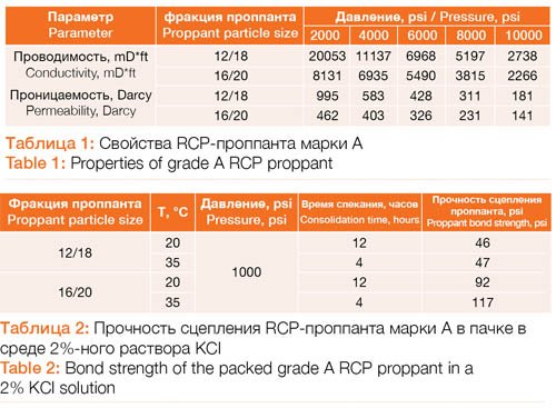
The properties of the A proppant that turned out to possess the most suitable characteristics are shown in Table 1 and 2 [1].
This paper discusses the results of the lab tests and initial findings of the field tests for the integrated RCP proppant chemical consolidation technology during HR at the VCNG terrigenous reservoirs.
Lab testing In accordance with the specification the A proppant is guaranteed to consolidate at a temperature above 20 оС. In view of this its bond strength it was required to be lab tested at a lower temperature.
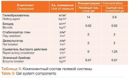
The physical modeling of the low temperature chemical consolidation was carried out for the sand packs in an HF fluid, a gel system (Table 3) used for HF at the VCNG fields.
The physical modeling included the A-RCP proppant curing processes both with and without an activator. An organic solvent served as an activator.
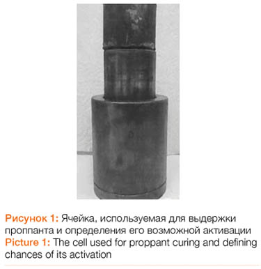
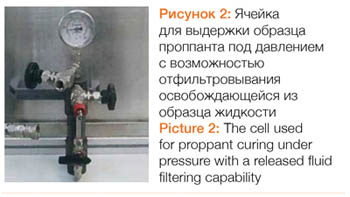
For consolidation, a proppant sample in a crosslinked gel was placed in the proppant crush cell (Picture 1) put inside another cell with a released fluid filtering capability to cure the proppant sample under pressure (Picture 2). Then the sample was maintained in a temperature control cooling incubator for 24 hours at a pressure of 68 atm (1000 psi).

The tester press to crush the sample and the pressure gage to measure the ulti-mate strength are shown in Picture 4.
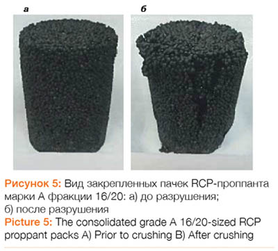
The test results showed that the grade A 16/20-sized RCP proppant sample meets the criterion for «no activation» during shipping or storage: Curing at a pressure of 0.1 atm for 3 hours and a temperature of 35 оС didn’t cause any consolidation.
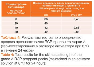 The tests showed that the chemical consolidation technology does not provide for enough consolidation of a low temperature RCP proppant pack to reach the desired strength to resist crushing assumed to be equal to 150 psi (10.5 atm) (Table 4) [5, 9]. During laboratory testing, the value of this parameter for the grade A 16/20-sized RCP proppant in the HF fluid was only 20-22 psi (1.36-1.50 atm). Use of an activator did not lead to any significant improvement in the proppant consolidation. The difference was 6 psi (0.46 atm) or 14.3% of the maximum value measured for demin-eralized water with the activator added (42 psi; 2.86 atm) and 18.7% without the acti-vator (36 psi; 2.45 atm).
Based on the lab test results that showed only a minor effect of the activator in consolidating the grade A 16/20-sized RCP proppant packs, it was decided not to use the activator for field testing.
Field Tests
Prior to field testing a number of risks were considered:
• RCP poppant curing on the surface caused by its improper storage (moisture ingress)
• Screenout conditions caused by the low temperature RCP proppant flowed through the string due to its surface activation by a heated water
• Uncertainty of the HF fracture location in a horizontal wellbore imposes the risks of inadequate estimated proppant quantity to reach the target consolidation. At the moment there is no established methodology to estimate it.
5 treatments were performed on the horizontal wells to assess the chemical consolidation capability for the low temperature grade A 16/20-sized RCP proppant and its likely risks.
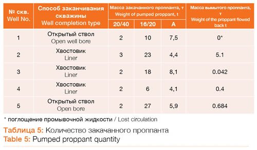
The HF design envisaged a sequential pumping of a 20/40 & 16/20-sized ceramic proppant and a low temperature grade A 16/20-sized RCP proppant (Table 5).
A coiled tubing fitted with a jet nozzle and the oil energized with nitrogen as well as a polymer and activator gelled oil was used for well completion and clean-up following HR. This system at varying polymer and crosslinker concentrations has an increased viscosity (150-400 cP) and a proppant carrying capacity. Due to a low reservoir pressure at completion and clean-up, lost (gelled oil) circulation occurred in 1 well that prevented the complete removal of the proppant from the well bore hole.
The field test analysis of the chemical consolidation technology for the low temperature RCP proppant showed that the grade A proppant does not connect to-gether at the bottom hole. However, the moisture sensitivity risks surfaced: Moisture introduced during storage and work led to sticking with a potential of a proppant pumping failure that may also later cause a disruption in the subsurface equipment operation.
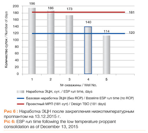
The consolidation performance was assessed based on the ESP run time, the time between overhauls (TBO). An average baseline TBO for the HF wells at VCNG is 120 days. To determine the efficiency of the grade A RCP proppant chemical consolidation technology we assumed a value equal to 181 days, which ac-counts for a reduction in the operating costs due to an extended ESP operation period and the proppant costs.
The test results for the grade A RCP proppant chemical consolidation technol-ogy and well operation monitoring outcomes yielded the TBO values shown in Picture 6. The current time between failures for 5 VCNG wells had exceeded the average ESP run time for the wells following HF by 42 days and kept growing. The designed 181 days were exceeded for 2 wells.
Keeping the proppant amount in the HF fracture supported an increase in the stable fracture performance during well operation including the increased drawdown cases.
The proppant consolidation results are as follows:
1. Cost reduction for well workover and coiled tubing to clean up the horizontal bore hole
2. Cost reduction for a replacement ESP
3. Well idle time prevention and a subsequent incremental oil production
Lessons learned
• The lack of a model to calculate the required quantity of the RCP proppant, regardless of its grade, necessitates an adherence to the accumulated experience for its service: From 15 to 40% of the total proppant delivered to the HF fracture. The RCP poppant will not provide for good consolidation if the weight of the pumped proppant is inadequate.
• The volume of the liner and open hole where the the RCP proppant will settle down not filling up the fracture shall be considered for calculating its pumping quantity for the horizontal wells.
• The efforts should be made for a thorough clean-up of the bore hole in the wells with a low reservoir pressure and lost circulation during completion and clean-up, for example, through the use of the highly viscous foams with a lower density but an adequate sand carrying capacity.
Conclusions
1. Testing of the resin coated proppant chemical consolidation technology proved its efficiency at low temperatures of the Verkhnaya Chona Horizon at VCNG. This technology is contemplated for implementation at every HF well.
2. When calculating the weight of the low temperature chemically consolidated RCP proppant, the horizontal well bore volume should be considered for the horizontal wells with a low reservoir pressure due to the difficulties of predicting the fracture propagation direction to ensure its adequate quantity in the HF fracture.
References – Список литературы
1. Economides, M.J. and Nolte, K.G. Reservoir stimulation, 3rd Edition. John Wiley Sons | 2000-06-09, 856 pages.
2. Andrews, J. S. and Kjorholt, H. Rock Mechanical Principles Help to Predict Proppant Flowback From Hydraulic Fractures // SPE 47382. 1998. 381-390.
3. Ely, J.W.and Arnold, and W.T. New techniques and quality Control Find Success in Enhancing productivity and Minimizing Proppant Flowback // SPE 20708. 1990.
4. Mohammad H. Alqam, Hazim H. Abass, Mirajuddin R. Khan, and Edwin T. Caliboso. Experimental Study on Additives Systems Used for Proppant Flowback Flowback Control in a Hydraulic Fracturing Treatment // SPE 106358. 2006.
5. Norman, L.R., Terracina, J.M., McCabe, M.A., and Nguyen, P.D.: “Applica-tion of Curable Resin- Coated Proppant,” SPEPE (Nov. 1992) 343-349.
6. Edelman J., Maghrabia K., Semary M., Mathur A., Samir Z. A., Bernechia J. M.. Rod-shaped of proppant provides proppant flowback control in the Egyptian eastern desert // SPE 164014. 2013.
7. Lyle H. Burke, Dana Roney, Lone, Tyler Elgar, Andrea Hersey. Factors That Impact the Performance of Resin Coated Proppant in Low Temperature Reservoirs // SPE 162792. 2012.
8. http://www.rcptechnology.ru/LtRCP
9. Anderson R.W., Johnson D.E., Diep T. New Resin Technology Improves Proppant Flowback Control in HP/HT Environments // SPE 77745-MS, 2002.
Authors
Denis Kushnarenko: Department Head, Project Management for New Technology, Verkhnechonskneftegaz
Danil Khoklov: Department Head, Well Technology, Verkhnechonskneftegaz
Rinat Kharisov: BHT Technology Lab Head, Chemistry PhD, RN UfaNIPIneft
Alexei Komissarov: Engineer, the RN GRP Research Center
Daria Ivanovskaya: Engineer, the RN GRP Research Center
This article was published in the Nauchno-technicheskiy vestnik OAO «NK «Rosneft» (№ 4, 2016, p. 56-59; ISSN 2074-2339).
Printed with the permission of the editorial team.