Verkhnechonskoye: Scale Management and Inhibition
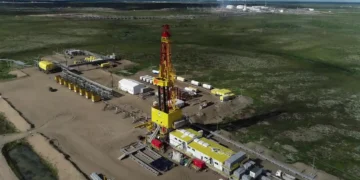
You could say that the first major day of oil production in Eastern Siberia was the first batch of oil produced from the Verkhnechonskoye Oil and Gas Condensate Field (VCNG), which is located in the north of the Irkutsk Oblast. But as the VCNG development progressed, processes limiting the oil and gas production cropped up.
One of the major issue was scale formation in the oil and gas wells. The most common oilfield scales are salts of varying chemical composition: sulfates, carbonates, sulfides, and chlorides. The VCNG scales are mainly halite (NaCl) chloride salts and gypsum (CaSO4×2Н2О) sulfate salts.
The salt deposit formation at the VCNG field is driven by its exceptional geology and geochemistry [1–3]:
• Low (12ºС) reservoir fluid temperatures dropping to -5ºС at the surface that is induced by gas evolution and permafrost effects
• Low reservoir pressure, 1.5 MPa average at the top of the reservoir (14.8 MPa in some wells which is below the bubblepoint); bottom hole pressure of 9–13.5 MPa and wellhead pressure of 2.5–3 MPa in the flowing wells
• High salinity (up to 500 g/dm3) of reservoir water and 1.29 – 1.30 g/dm3 for chloride calcium brines
• Reservoir salinity (50% or more of the pore space plugged with halite) and salinity dilution when the injected fresh water of the reservoir pressure maintenance (RPM) system permeates the formation [4].
The major oil production at VCNG is from the terrigenous formations of the VCh1, VCh2, VCh1+2 Vendian Verkhnechonskoye horizons.
Chloride Scaling
Salt deposits in the oil wells exist from the surface to the bottom hole area (BHA) and are mainly sodium chloride or halite [2]. The fundamental difference between the halite deposit compared to standard conditions, is the fact that when there is low water content in the produced water-in-oil emulsion, salts precipitate. While the paper by Kashchavtsev and Mishchenko [5] says that chlorides form only in inverse emulsion (oil in water). Yet the halite crystals at VChNGKM are present even in dry oil (0.03% water content) as micro-grains [4].
Halite deposit structures vary in the wells.
• When the water cut of the produced oil is low (from 1 to 10%), the deposits are the sodium chloride crystals which are adsorbed by the resin, asphaltene, and paraffin deposits on the walls of the downhole pumps or casing strings (Fig. 1). The halite crystals were most frequently observed to form in the production wells where it proved cumbersome remove the high density brines. High concentration brines accumulate at the bottom hole in perforated or open zones with low permeability and porosity [2].

• When the water cut of the produced oil is high (from 10 to 99%) the deposits gets dense (Fig. 2). The source of halite is two types of produced water. The first type is the fairly strong (E. V. Pinneker’s classification) natural formation brines. The brine chemical composition is calcium chloride based on the most prevalent ions with a salinity from 50 to 500 g/dm3 and a specific gravity up to 1.3 g/cm3 [1, 2]. The second type is production induced sodium chloride water. It forms when the salinity of the terrigenous formations of the Verkhnechonskoye horizon, whose pore space is occupied with halite, is diluted by injected water. Eventually the salinity of injected water rises from 50-
70 to 365 g/dm3 and its specific gravity goes up to 1.2 g/cm3 (the first year of water breakthrough to the well). The mixing of such water in the formation heightens halite formation if there is a geochemical barrier. Sodium chloride does not only occur in the wells but also in the bottom hole area [2, 6, 7].

The only efficient halite removal technique currently used at VCNG is a normal and cross-over water wash combined with hot oil wash. The technique for fresh water well treatment to prevent halite formation can be further improved by adding the chelates, HEDP (1-Hydroxy Ethylidene-1,1-Diphosphonic Acid) or ATMP (Amino Trimethylene Phosphonic Acid). Most importantly, washing with the chelates added to the process liquids is essential for high salinity water. The chelates further inhibit scale (halite, gypsum, and calcite) formation in the wells treated. A currently effective amount of the inhibitor (chelate) is added to water for normal wash of the electric pumping unit (ESP) or a 5% aqueous solution is prepared for cross-over wash. A combined use of both the chelates and 20% aqueous caustic soda provides for removal of the hydrated gas deposits in the annular space through heat emission during substance mixing.
If the produced water in the well is entirely production induced, the number of water washes decreases with a decrease in the salinity of injected water because of the salt removal from the sandstone rock formation. The experiments conducted on the Verkhnechonskoye horizon sample showed that the amount of water required for its complete salinity dilution is equal to the rock pore volume times 62 – 161 [2]. For example, 3–4 fresh water washes were done monthly in the Х010 well at a produced water salinity of 1.19 g/cm3 in early 2012 while only one wash per month was required at a produced water salinity of 1.095 g/cm3 as early as in 2014.
Large fresh water squeezes are done in wells with halite deposits in the BHA that help to restore the well production level. The first case of halite re-depositing in the BHA was observed for the Р-Х7 well when the previous HCl (6%), hot water and oil washes of the downhole pumping equipment failed to restore the well operating parameters. The liquid rate went down from 300 to 80m3/day while productivity index dropped from 80 to 10 m3/(day⋅MPa). Following the temperature and pressure data interpretation the BHA was washed with 60m3 of water that restored the well standard production level and flow rate [2]. To prevent hydrate formation during water wash in the wells with low injectivity or ESP capacity (up to 90m3), the wash should be with 10% aqueous hydrate solvent inhibitor (90–95% methanol content). This solution prevents both hydrate formation and water freezing in the cold Verkhnechonskoye wells by raising the freezing point of water to -6ºС.
Sulfate Scaling
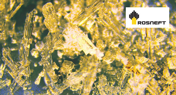
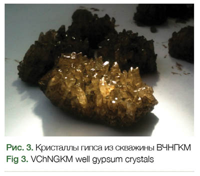
The gypsum sulfite deposits are present in the oil wells from their mouth to BHA when water cut exceeds 30% [3]. Gypsum occurs as the 0.5 – 1.5 mm transparent brown crystals (Fig. 3). There are no gypsum deposits in the VCNG wells, their BHA, or high or low pressure water lines in the RPM system.
According to the field tests and this simulation [3], gypsum in the VCNG production wells is produced by mixing production water with a high sulfate ion concentration (up to 600mg/dm3) and calcium chloride formation brines with a sulfate ion concentration of 0 – 154mg/dm3 and a calcium concentration up to 115g/dm3. The source of the sulfate ion is the VCNG water wells. Fresh water for the RPM system is produced by water wells from the bicarbonate geochemical area of the Upper Lena suite and the sulfate geochemical area of the Upper Lena and Litvintsev suite base. The dynamic liquid level in some of the wells decreases with water supply depletion, which adds to the BHA drawdown and shrinks the piezometric surface of the Upper Lena aquifer system. As the piezometric surface of the Upper Lena suite reduces down to the evel below, the Litvintsev suite piezometric surface level (the sulfate geochemical area) the saline sulfate water upsurges to the VCNG water wells [3, 8]. In other wells with a depth exceeding 90 m (120–300m) the ground water is inherently characterized by a high sulfate ion concentration (up to 2,500mg/dm3).
The PAO VCNG Upstream Chemistry Team developed and introduced a rapid test to identify future oil wells with gypsum formation based on which a gypsum salt deposit diagram was produced (Fig. 4). The test is rooted in specific gravity fluctuation types and salinity of the produced water. Thus a linear decrease in produced water’s specific gravity or its high value (1.3g/cm3) does not lead to gypsum depositing. While a sharp drop in specific gravity from 1.3 to 1.1–1.4g/cm3 indicates a probable gypsum formation [7].
The research results of ground water interaction specifics in the Verkhnechonskoye horizon support identification of the current active and expected scale depositing area in the diagram that facilitates operation of the inventory of problematic wells. The field data shows that water interacts most actively in deposit area 3 (see Fig. 4), where the is water present in the reservoir portion, and in zone 1, in which there may be limited reservoir formation waters. [9]. Interaction in area 2 is attributed to a conductive fault between the graben and the second VCNG fault block. Areas 4–6 are prospective as they contain a water part of
the deposits.

Hydrochloric acid treatment to prevent gypsum depositing is not used at VCNG because of low subsurface temperature (about 9ºС at the bottom hole and up to 5ºС at the surface). Gypsum deposits in the downhole pumping equipment and well are removed by 20% aqueous caustic soda (NaOH) with a removal efficiency of 90%. The back pressure valve is removed in advance on the ESP installation. If gypsum builds up inside the capital string or liner a 20% aqueous caustic soda alkali soaker is preliminarily installed before bottom hole cleaning during well servicing. This measure means that the saw tooth or drill bit tool can penetrate at least twice the rate in the trouble section of the string. 20% aqueous caustic soda is injected for dispersion to dislodge gypsum deposits in BHA with a subsequent BHA treatment with 12% aqueous hydrochloric acid to remove water insoluble resultants of alkali and gypsum reaction represented by quick lime, Са(OH)2.
The HEDP or ATMP chelates (a minimum active substance concentration of 40%) as scale inhibitors are used to prevent gypsum depositing in the downhole equipment. A scale inhibitor is employed on the entire problematic inventory to an extent of 100%. The inhibitor is fed to the well by a continuous injection to the annular space with a chemical batching unit (UDR). The process efficiency is monitored by tracking the downhole equipment operation and analyzing well and ESP operation. Further, a wellhead sampling is done to identify the residual phosphonate concentration in produced water. Currently the issue of gypsum depositing in the production well BHA is settled. Laboratory research was conducted, and the units for feeding scale inhibitor to the reservoir (10% aqueous ATMP in 2% aqueous muriate of potash) were developed. Introduction of efficient chemicalization at VCNG increased the average time between failures for the inventory of the scale problematic wells from 282 days in 2014 to 537 days in 2015.
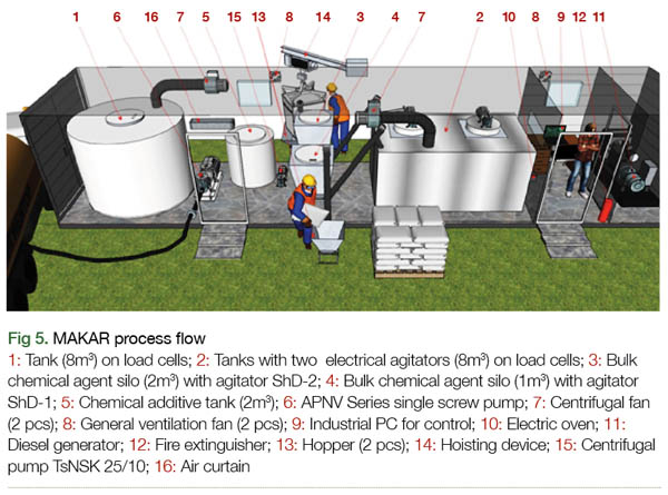
Judging from the operating experience at VCNG located in a remote area in the Extreme North, the major issue of chemicalization in this area is a high cost of chemicals. This is caused by a complicated logistics and calls for having a safety stock in the event of chemical short delivery. A practical solution to the issue is to set up commercial chemical production directly in the field. It will aid in cutting down logistic costs, curbing the risk of low quality chemical delivery with reduced active component content, and tightening process control of commercial chemical production by the company. Use of summarized chemicals with water as a solvent will further shrink the commercial chemical unit cost. A mobile 40-foot containerized, automated chemical activation package (MAKAR) can be used to prepare chemical liquids [10] (Fig. 5).
Field trials of the proprietary scale inhibitor formulations developed specifically for the VCNG process and geological circumstances are scheduled for 2016. Commercial chemicals will be prepared in the field with water used as a solvent for the summarized chemicals. Several chemical injection technologies including continuous injection to the well annular space by UDR and BHA squeezing will be tested. It will kick off a new stage of chemicalization in the mechanized inventory of the Verkhnechonskoye Oil and Gas Condensate Field.
Carbonate Scaling
Currently the carbonate buildups occur at VCNG as a slight calcite (CaCO3) scaling (less than 1 mm) on the downhole motor surface and as contamination in the oil well production. Carbonate depositing at VCNG may aggravate in its fourth development stage as water cut of the well inventory swells to 90%. Such scaling in the downhole equipment and BHA can be removed with 6% and 12% aqueous hydrochloric acid respectively. Carbonate scale forming is most effectively prevented by the HEDP scale inhibitors.
Summary
Hydrocarbon production chemicalization at all process stages is, at this point, one of the most paramount and efficient ways to ensure operability of the downhole and surface equipment. The Verkhnechonskoye Oil and Gas Condensate Field is one of the earliest remote large scale oil production projects in the Extreme North of the Eastern Siberia with no extensive infrastructure. Accordingly, the successful production and scientific experience of scaling control accumulated during VCNG operation can be used to develop the new far-flung oil and gas fields in Extreme North including the Russian Arctic Shelf.
References
1. Pinneker E.V., Brines of Angara-Lena artesian basin, Moscow: Nauka Publ., 1966, 332 s.
2. Chertovskikh E.O., Lapoukhov A.S., Kachin V.A., Karpikov A.V., Problems of oil and gas production in the Verkhnechonskoye oil and gas condensate field associated with halite depositing, SPE AFE, 2013, pp. 1491–1527.
3. Chertovskikh E.O., Alekseev S.M., Problems of oil and gas production in the Verkhnechonskoye oil and gas condensate field associated with gypsum depositing, SPE, ROG, 2014, pp. 1–17.
4. Kachin V.A. Chertovskikh E.O. Karpikov A.V., Effects of Verkhnechonskoye horizon saline sandstone on oil and gas production in Verkhnechonskoye Oil and Gas Condensate Field // Izvestiya Sibirskogo otdeleniya sektsii nauk o Zemle RAEN, 2013, no. 1 (42), pp. 129–134.
5. Kashchavtsev V.E., Mishchenko I.T., Salt formation in oil production, Moscow: Orbita-M Publ., 2004, 432 p.
6. Shvartsev S.L., Pinneker E.V., Perel’man A.I. et al., Fundamentals of hydrogeology. Hydrogeochemistry), Novosibirsk: Nauka Publ., 1982, 286 p.
7. Chertovskikh E.O., Alekseev S.V., Collected papers Geology and oil and gas potential of West Siberian megabasin (experience, innovation), Tyumen: Publ. of TSOGU, 2014, pp. 168–171.
8. Shenkman B.M., Verkhnechonskoye Oil and Gas Condensate Field ground water chemistry (VChNGKM)// Izvestiya IGU. Sektsiya Nauki o Zemle. 2013, V. 6, no. 1, pp. 206-222.
9. Chertovskikh E.O., Kachin V.A., Karpikov A.V., Halite depositing during oil and gas production in Verkhnechonskoye Oil and Gas Condensate Field // Vestnik IRGTU, 2013, no. 5, pp. 82–91.
10. Klushin I.G., Chertovkikh E.O., Kunaev R.U., Buglov N.A., Prospects for use of active chemicals in the Arctic and Extreme North oil fields // Izvestiya Sibirskogo otdeleniya sektsii nauk o Zemle RAEN. Geology: Ore field prospecting and exploration, 2015, no. 3, pp. 53–60.
N. V. Kalinkina, E. O. Chertovskikh, R. U. Kunaev, PhD Chemistry (PAO VChNG),
I. G. Klyushin (NK Rosneft)
A. G. Vakhromeev, PhD Geology and Mineralogy (RN Drilling Irkutsk Brach)
S. V. Alekseev, PhD Geology and Mineralogy (Institute of Earth Crust, RAS SB)
The article was published in the ROSNEFT Scientific and Technical Newsletter (Nauchno-technicheskiy Vestnik OAO “NK “Rosneft”) No.1, 2016, pp.52.
Printed with permission from the Editorial Board.