Well Navigation Process: Application of Traffic Light Communication System and Target Changing Methods in Geosteering

For Part One of this article click HERE
For Part Two of this article click HERE
Geosteerer – Directional Driller Duo
For all geosteering approaches, what is precisely known is limited and sporadically located along the wellbore trajectory. When geosteering is required, there is no substitute for geologic and engineering knowledge of the area being drilled, the critical ability to approximate reality sufficiently well and to make informed directional steering decisions. Therefore, the human aspect of geosteering should never be forgotten or underestimated. Regardless of the most advanced tools used for geosteering, the ultimate and most crucial question whether “to steer up or steer down?» will always be answered only by a geosteerer and executed by a directional driller.
The relationship between the geosteerer and directional driller is the most crucial and imperative of all for the ultimate success of the geosteering process.
This article describes in detail the most critical aspects of the communication process between the geosteerer and the directional driller; frequency of the commands, type of information as well as particular circumstances in which the information should be conveyed.
Communication with the Directional Driller
A geosteerer is a person who through real-time data analysis and interpretation owns all the information needed to guide the well within a thin laterally distributed target. Yet it is the directional driller who can physically steer the well towards the right direction. A well-established relationship between a geosteerer and directional driller often determines the final success of the operation.
The time spent to improve the geosteerer – directional driller relationship should be prioritized and included in the overall cost of any geosteering operations. It is recommended that the geosteering team, the geosteerer and directional driller, should spend value-creating time before drilling, dedicated to verifying expectations on both sides and confirming mutual objectives of the geosteering. Understanding the geosteerer’s intentions will allow the directional driller to respond more accurately.
It is also paramount to create communication in both directions. Directional drillers possess better comprehension of the BHA capabilities and its reactions to the directional changes when properly exploited. This will benefit the overall steering operation, with manoeuvres being executed effectively and efficiently. Hence, both sides are equally responsible for developing a strong relationship.
The Key Information Needed to Navigate a Horizontal Well
One of the geosteerer’s most important tasks is to communicate steering directions to the directional driller. To establish adequate steering direction, the geosteerer needs to establish four key data portions:
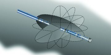
1) Position of the bit in the three-dimensional space
One way to display a position of the bit in the three-dimensional subsurface is by using X, Y, Z coordinates (figure 1). If geological targets are defined by X, Y, Z coordinates, a three-dimensional distance between the bit and the geometrical target can be measured. The coordinates, however, do not provide information about the bit position in relation to the actual reservoir location. They also do not specify the actual position of the target in relation to the actual reservoir location.

2) The stratigraphic position of the bit
The stratigraphic position indicates the position of the bit in relation to the reservoir target (e.g. particular stratigraphic subunit of the reservoir – see figure 2) It determines the vertical and horizontal distance (e.g. in feet) to the target (if outside the target) and a relative distance to the bottom and top of the target (if in the target.)

Knowledge of the bit’s stratigraphic position allows specifying the geometrical boundaries of the targeted reservoir at a given position of the borehole; and determines the amount of room above and below the bit in case a change of drilling direction is required (as long as the vertical and lateral dimensions of the targeted reservoir are known.) This is partially resolved by the TVDSS measurement from the survey measurement as the bit position can be concluded from the anticipated thickness of the targeted reservoir. It should be taken into account however, that the horizontal thickness of the target may vary significantly along the well path.
3) Formation dip
In order to adjust a trajectory inclination accordingly and maintain a borehole within the target zone, a formation dip needs to be estimated (figure 3). Continuous formation dip calculation enhances the structural interpretation and provides lateral differences in the stratigraphic thickness of the reservoir.

It is important to differentiate between apparent and true dip as these two represent different geometrical features of the formation being targeted. The most accurate measurement of the formation dip is provided by the borehole azimuthal images.
It should be noted that in the event the borehole is drilled along the strike of the formation bed, it would not be possible to estimate the actual formation dip value (neither apparent nor true formation dip).
4) Impediments that cannot be anticipated prior to drilling
This may include faults or any other unforeseen prior to drilling obstacles (figure 4). The location of sub-seismic faults (with a throw smaller than 30 feet which is on average seismic detection limit) is usually impossible to foresee. Although general knowledge of the areas with sub- seismic faults prevalence might exist prior to drilling, such small faults tend to propagate to limited distances. Usually, there are also no control wells to provide information about their accurate position. Virtually, the only option is to try to identify them along the drilled section and respond immediately to any sudden trajectory placement outside of the desired target zone.

Another common obstacle impossible to fully mitigate before drilling can be chert rich horizons which are abundant especially in chalky reservoirs. This very hard rock made of silicon oxide (also called flint) often causes damage to BHAs and significantly impedes steering capabilities of any bottom hole assembly. When trapped below/above a chert rich horizon, the hardness of the cherty rock causes the bit to be pushed away or deflected, resulting in a recurrent need for readjustment of the drilling direction. Although it is nearly impossible to predict the cherty horizons along the drilled well, it is still achievable to successfully drill through the cherts with the application of a sufficient angle of attack.
A Geosteerer must perform his/her duties in such a way that all the four key data portions are known at every moment of the drilling operation for every point on the well trajectory.
S.M.A.R.T. Communication
Having acquired the knowledge of all four key information portions at any given point of the drilled trajectory, the geosteerer needs to deduct the most optimal steering direction and communicate it to the directional driller.
The steering direction message must fulfil certain objectives:
• It must be shaped in a clear and logic fashion, easily comprehended despite the circumstances (e.g. under stress);
• It must be passed to directional driller regardless of the amount of time available for communication (e.g. in a rush);
• It must be suitable for any communication equipment used between the geosteerer and directional driller (e.g. phone, text, messenger, face to face chat.)
In other words, the message needs to be agile and S.M.A.R.T. (S.M.A.R.T. acronym as per George T. Duran, 1981; – Specific, Measurable, Attainable, Relevant and Time-based):
1) Specific
There should be a clear understanding of the meaning of the log response and the appropriate course of action to be taken. Premature well placement instructions are too often given because of the initial misinterpretation of tool and sensor’s responses. The only reason to change the inclination of a well path is because of the change in geology. Additionally, all steering decisions should utilize and follow all the available geologic and engineering data, not only selective parts of them.
2) Measurable
Requested changes to the well path should be stated using numbers to define the required well inclination, TVD, and MD. Additionally, a quantitative adjustment should specify the TVD and well inclination needed at a given MD. Using descriptive commands is not an option here.
3) Attainable
Requesting an impossible manoeuvre from the directional driller is not “S.M.A.R.T.”. Each BHA has different steering capabilities and limitations that should be considered. These capabilities and limitations should be clearly communicated and commonly known. There is no point asking for a given dogleg across a certain interval which the BHA is unable to deliver.
4) Relevant
By default, a change of steering direction should occur only when an evident prerequisite arises and not based on a premonition that something might occur. The steering adjustment must also be adequate to the circumstances. A drop of inclination that requires exceeding a dogleg limitation of 3 degrees can be only justified in a hazardous situation with the potential of exceeding a targeted reservoir.
5) Time-based (or better MD based)
It is never sufficient to request a change in TVD without specifying in what MD distance the requested TVD should be achieved. This distance will also determine the required inclination (and the DLS) to perform the manoeuvre. Please note that the same TVD value requested to be achieved within two different MD distances will result in two different inclination values required for the manoeuvre.
Traffic Light Communication System
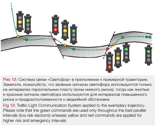
One of the most agile communication methods used between the geosteerer and the directional driller is called the Traffic Light System. The system is an effective and efficient way to communicate quickly and without unnecessary misunderstandings.
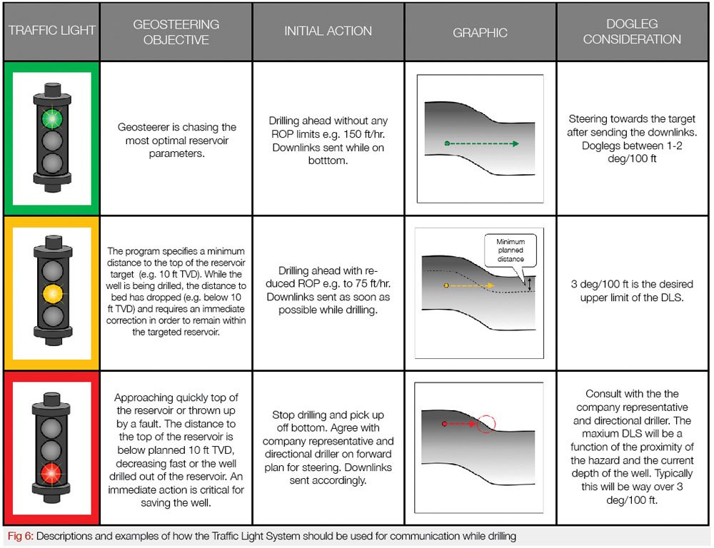
The geosteerer by defining the colour of the manoeuvre (green, yellow or red) and communicating it the directional driller sets the urgency and establishes a fashion in which the adjustment will be performed. This obviously will depend on the situation and circumstances. Identified criticality will allow the directional driller to immediately estimate how fast the manoeuvre needs to be performed, what steering ratio he/she should apply to the tool and what values of DLS and ROPs are required for a given adjustment. The Traffic Light System not only allows the message to be conveyed, but also “describes” the surroundings the BHA will have to deal with. Please see figures 5 and 6 for more details.

The Traffic Light Communication System includes:
• Green command
A normal, non-urgent manoeuvre within the targeted reservoir. Typical DLS ranges up to 2 – 2 ½ degrees per 100 feet (or any other DLS agreed pre-drill), the ROP is non-restricted, downlinks are sent while drilling and the steering ratio is set at around 50%. Azimuth and inclination can be adjusted simultaneously.
• Yellow command
Serious urgent manoeuvre when a well is approaching or has already reached the top or the bottom of the reservoir and a significant change of steering direction is required. Typical DLS still ranges up to 3 degrees per 100 feet, the ROP is restricted to allow downlinks to be received before a substantial distance is drilled. The steering ratio has increased to approximately 70%. Vertical adjustment takes precedence over the azimuthal changes.
• Red command
Critical emergency manoeuvre which if not executed properly may result in losing the well. The red command situation may arise when e.g. a well has drilled out of the reservoir into the overburden. The exact DLS values for the red manoeuvre will be a result of specific circumstances and conditions for each trajectory adjustment and BHA steering capabilities. Usually, they can reach way above 3 degrees per 100 feet. The drilling should be ceased, and the downlinks should be sent without any additional footage drilled. Consultation and agreement between all parties are required. Usually, in such circumstances, the directional driller will use full 100% steering ratio tool capabilities.
Target Changing Methods
Once a specific urgency of the manoeuvre has been established and communicated to the directional driller, it is important to also convey a new target for the new steering direction.
This can be obtained in two ways:
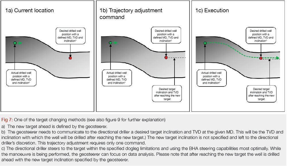
1) By specifying inclination and TVD at the MD distance within which the required TVD should be achieved
Here the geosteerer decides on the new target ahead (with XYZ coordinates) and the inclination of the well at the new target (more specifically – inclination from the new target onwards). The geosteerer does not specify the inclination which the directional driller needs to use to reach the new target and leaves in his/her hands the decision of how to perform the manoeuvre. Please note that in this situation the directional driller has the freedom to perform the adjustment with the inclination and steering ratio of his choice.
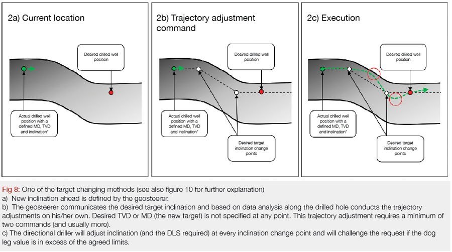
2) By specifying a new target inclination
Here the geosteerer calculates and decides on his/her own what inclination will be required for achieving an objective of moving the well by x feet TVD and within x feet MD distance. The directional driller executes the manoeuvre by setting the required build or drop rate of the tool. Please note that in this situation the directional driller is not aware of the new target nor of the inclination required at the new target (the XYZ coordinates of the new target and the inclination at the new target are not specified.)
Typically, through the usage of this type of target changing method (with changing the inclination only and not specifying the actual new target ahead), the well will continue traversing through the stratigraphy indefinitely (inclination lower /higher than formation dip.) It is common to mistakenly assume that this way the more optimal zone will be searched and found. This flawed belief is very risky and should not be accepted.
Usually, the type two manoeuvre produces much steeper inclinations (see red circles) as well as higher DLS. The trajectory shape also has more sinusoidal shape. The inclination at the new target is also not specified (more specifically – inclination from the new target onwards.) The directional driller is also unaware of the geosteerer’s objective and therefore she/he is unable to adjust the steering ratio accordingly or the most optimal point of drop/build commencement.
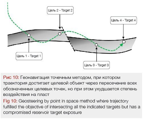
This is not the preferred case. Whenever possible, a target TVD and inclination at a given MD should be specified (see also figure 10 for further explanation.)
The above mentioned examples are the most common ways of target changing while geosteering. Often the actual consequences of using one method over the other one are not easily explained and expounded to the general public (and especially to the geosteering teams.)
They can be summarised and systematized as follows:
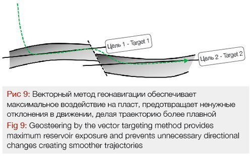
1) Vector targeting method (also called “drilling on a line”)
This method assumes that a target is a line with a given dip. The vector targeting method creates smooth transitions between the targets and gives sufficient flexibility to the directional driller to land on a target (on a line). In the event the geological surroundings push for a target change, a new target line – a certain inclination with certain horizontal tolerances – is given to the directional driller so a well can be landed on a new target.
2) The point in space method (also called “drilling on a point”).
The point in space method for steering horizontal wells relies on a geosteerer deciding on the new target inclination that a well path will be drilled. The geosteerer relies only on her/his skills of calculating the inclination required to intersect a TVD target at a certain point of a horizontal section (at certain MD of the well). Although this method often allows intersecting all the indicated new targets, at the same time it provides very little control over the inclination of the wellbore between the target points since the directional driller is not involved in the selecting inclination values process. This approach regularly creates “over-shooting” of the targets with necessary corrections of the well path immediately after reaching the target. Consequently, this reduces flexibility for directional drillers and generates more work for the entire geosteering team. The method also usually involves a higher number of commands. In some cases, the undulating shape of a trajectory can cause losing the well. The figure below represents a trajectory that intersected all the required targets but still exhibits compromised reservoir exposure. Note that all the targets can also be intersected with a much smoother trajectory.
Conclusions and Recommendations
The geosteerer must endeavour to select the safest position of the wellbore at all times, a position which allows the fastest reaction to the change in geology and the shortest wellbore path that refrains from misplacement of the trajectory outside of the targeted reservoir.


The primary position of the wellbore is parallel to the dip of the targeted formation bed. Any other position (any other wellbore path inclination) is considered a higher risk position and should be avoided if possible or reduced to a necessary minimum (figure 11). The higher risk position is also called a transport section of the well path.
Bearing in mind the low and high risk sections (marked on figure 11 by green and red intervals), it is recommended to use green commands during the bed parallel sections and while traversing through the stratigraphy or outside of the targeted reservoir – yellow and red commands.
Similarly, it is recommended to use the drill on a point method (point in space method) only within the low risk sections (see green intervals in the figure 11). The drill on a point method is acceptable here as the well is being drilling parallel to the dip of the targeted formation bed and the trajectory requires only minimal adjustments of the inclination. As soon as the well starts traversing through the stratigraphy, reaches hazardous position in relation to the reservoir boundaries or exits the targeted reservoir, the drill on a line method (vector targeting method) should be applied.

About the Author
PIOTR PRZYBYLO has acquired crucial technical and business skills that enabled him to drill some of the deepest and longest wells in the world. He bridges the gap between the technical and commercial sides of the upstream oil and gas industry. He is the Founder of GEOMODES, a company that educates future experts in the field of geosteering and optimizes team organizational structure for efficient skill utilization. He is also the author of HORIZONTAL WELL GEOSTEERING GUIDELINES (Amazon)- first ever published comprehensive manual which is a must-have for every geosteering expert.
Reach out to author: piotr.przybylo@geomodes.com